Illumination device for video presenter and video presenter having the same

Inactive Publication Date: 2006-07-13
HANWHA TECHWIN CO LTD
View PDF12 Cites 5 Cited by
  • Summary
  • Abstract
  • Description
  • Claims
  • Application Information

AI Technical Summary

Benefits of technology

[0014] The present invention also provides an illumination device for a video presenter, which can distribute illumination light over the outer surface of a target object more evenly so that different portions of the object can be rendered with almost the same illumination intensity, and a video presenter having the illumination device.
[0015] The present invention also provides a video presenter and an illumination device for the video presenter, which is easy to keep and manipulate.

Problems solved by technology

Therefore, after a long period of use, the rotation joints may substantially be worn out or loosened.
With this illumination device, however, light cannot be evenly distributed throughout the target object area.
Therefore, in such a device where the illumination device is provided at only one lower side of the target object, it is difficult to apply light to the target object with an adequate incidence angle.
However, because the reflection plate is fixed on the table of the video presenter, it is not intended to adjust its orientation for a better illumination.
Thus, if the operator attempts to adjust the reflection plate, she can be injured by the reflection plate or the reflection plate may be damaged or deformed beyond its design limit.
Since the light source is a distance apart from a target object, the target object may suffer from lack of sufficient illumination.
In order to increase the illumination intensity of the light source, however, a considerable amount of energy should be consumed, which may often cause noises in circuits near an optical photographing system.
In addition, there is also a possibility of image deformations especially when the surface of the target object is reflective.
Therefore, the structure of the video presenter inevitably becomes complicated, which results in an increase in the manufacturing costs of the video presenter.

Method used


Image

  • Illumination device for video presenter and video presenter having the same
  • Illumination device for video presenter and video presenter having the same
  • Illumination device for video presenter and video presenter having the same

Examples


Embodiment Construction

[0056] The present invention will now be described more in details with reference to the accompanying drawings, in which exemplary embodiments of the present invention are shown.

[0057]FIG. 3 is a perspective view of a video presenter according to one exemplary embodiment of the present invention. FIG. 4 is a side view of the video presenter of FIG. 3, and FIG. 5 is a plan view of the video presenter of FIG. 3.

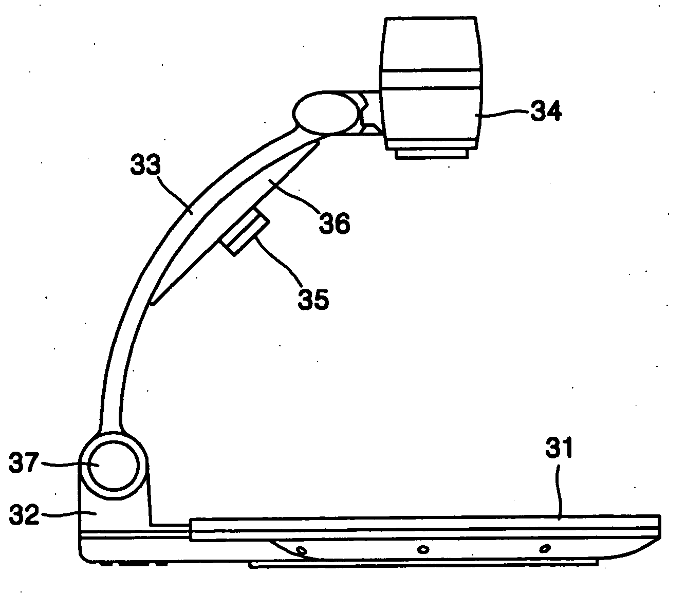
[0058] Referring to FIG. 3, the video presenter includes a table 31 formed generally in a circular and flat shape for placing an object thereon, a supporting base 32 at one lateral side of the table 31, a support arm 33 rotatably coupled to the supporting base 32 and preferably formed in a generally arch-like shape, and a camera head 34 rotatably coupled to an upper end of the support arm 33. The support arm 33 is pivotally connected to the supporting base 32 so that it can rotate about a pivot shaft 37. The camera head 34 is pivotally connected to the support arm 33 so that ...


PUM


Abstract

A video presenter includes a table, a supporting base disposed at one side of the table, a support arm formed in a generally arch shape and rotatably coupled to the supporting base, a camera head rotatably coupled at an upper end of the support arm, a lamp holder attached to an inwardly facing surface of the support arm, and a lamp unit rotatably coupled to the lamp holder and including a lamp cover having a curved inner surface with a varying radius of curvature. The lamp cover may have a plurality of prisms at its inner surface.

Description

BACKGROUND OF THE INVENTION [0001] 1. Field of the Invention [0002] The present invention relates to a video presenter, more particularly, to an illumination device for illuminating a target object placed on a video presenter. [0003] 2. Description of the Related Art [0004] Video presenters are devices that input and display an image of a target object taken typically by a charge coupled device (CCD) camera on a display unit for academic or commercial purposes. Particularly, a video presenter can obtain an enlarged image of the target object taken from the CCD camera by coupling a magnifying lens to the CCD camera and can display the enlarged image of the target object on the display unit. The video presenter may include an illumination device for improving the definition of an image of the target object taken by the CCD camera. The illumination device should appropriately illuminate the target object while preventing itself from interfering with a camera head of the CCD camera. The...

Claims


Application Information

Patent Timeline
IPC IPC(8): G02F1/1335
CPCG03B15/035G03B17/04G03B29/00
Inventor YOON, YONG-GYULEE, SEUNG-YEOBYOO, MYUNG-HO
Owner HANWHA TECHWIN CO LTD
Why Eureka
Try Eureka