Check patentability & draft patents in minutes with Patsnap Eureka AI!

Transceiver boot loader

a technology of optical transmitters and bootloaders, applied in the field of optical transmitters and receivers, can solve the problems of inflexible controller functionality, fast operation, limited controller hardware structure, etc., and achieve the effect of facilitating user operation, facilitating user customization, and facilitating user customization

Active Publication Date: 2006-07-13
II VI DELAWARE INC
View PDF2 Cites 5 Cited by
  • Summary
  • Abstract
  • Description
  • Claims
  • Application Information

AI Technical Summary

Benefits of technology

[0011] Accordingly, in order to change the functionality of the optical transceiver, the hardware of the optical transceiver need not change at all. Instead, different microcode is written to the persistent memory to implement the change in functionality. Loading different microcode into persistent memory is significantly more straightforward for a user than purchasing and setting up a different optical transceiver.
[0012] Furthermore, the addition of the loader microcode eliminates the prior requirement that such microcode be provided to the transceiver for every update, and ensures that the loader microcode will be available for future microcode updates. Therefore, the principles of the present invention allow for more flexible operation for the optical transceiver at a greater convenience for the user.

Problems solved by technology

Their operation is fast, but inflexible.
Being primarily state machines, the functionality of the controller is limited to the hardware structure of the controller.

Method used


Image

  • Transceiver boot loader
  • Transceiver boot loader
  • Transceiver boot loader

Examples


Embodiment Construction

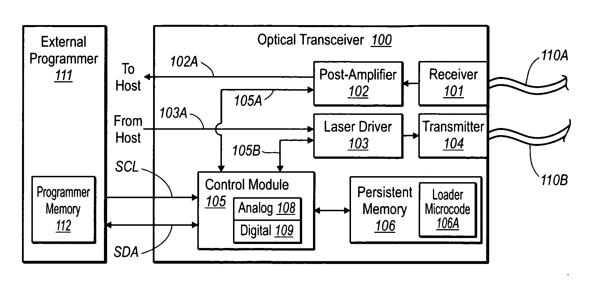
[0018] The principles of the present invention relate to an operational optical transceiver configured to implement a transceiver boot loader. The optical transceiver includes a processor and a persistent memory. The persistent memory includes a portion of memory that is write-protected and configured to comprise the transceiver boot loader. The transceiver boot loader contains loader microcode that when executed by the processor causes the optical transceiver to update other microcode stored in the persistent memory. The transceiver loads the new microcode and then verifies that the microcode update is complete. An example operational optical transceiver environment will first be described. Then, the operation in accordance with the invention will be described with respect to the operational environment.

[0019]FIG. 1 illustrates an optical transceiver 100 in which the principles of the present invention may be employed. While the optical transceiver 100 will be described in some de...


PUM


Abstract

A method for dynamically updating an optical transceiver (or optical transmitter or optical receiver) that has at least one processor and persistent memory that includes one or more write-protected memory locations. The write-protected memory locations of the persistent memory includes loader microcode that, when executed by the at least one processor, causes the optical transceiver to have access to a first set of functionality. In order to implement the invention, the optical transceiver first processes received microcode. Then, the processed representation of the received microcode is written to the persistent memory outside of the one or more write-protected memory locations. The optical transceiver then determines that all of the microcode that is to be written, to the persistent memory during the update has been written to the persistent memory. Finally, the persistent memory is altered to reflect that the update is complete.

Description

CROSS-REFERENCE TO RELATED APPLICATIONS [0001] This application claims the benefit of U.S. Provisional Application No. 60 / 631,740, filed Nov. 30, 2004, which is incorporated herein by reference in its entirety.BACKGROUND OF THE INVENTION [0002] 1. The Field of the Invention [0003] The present invention relates generally to optical transmitters and receivers. More specifically, the present invention relates to optical transmitter and receivers that are capable of running different versions of microcode to manage its operation. [0004] 2. Background and Relevant Art [0005] Computing and networking technology have transformed our world. As the amount of information communicated over networks has increased, high speed transmission has become ever more critical. Many high speed data transmission networks rely on optical transceivers and similar devices for facilitating transmission and reception of digital data embodied in the form of optical signals over optical fibers. Optical networks ...

Claims


Application Information

Patent Timeline
IPC IPC(8): H04B10/00
CPCH04B10/801
Inventor DYBSETTER, GERALD L.EKKIZOGLOY, LUKE M.HAHIN, JAYNE C.
Owner II VI DELAWARE INC
Features
  • R&D
  • Intellectual Property
  • Life Sciences
  • Materials
  • Tech Scout
  • Unparalleled Data Quality
  • Higher Quality Content
  • 60% Fewer Hallucinations
Learn More