Touch-sensitive interface

a touch-sensitive interface and tactile technology, applied in the field of touch-sensitive interfaces, can solve the problems of system bulkyness and complicated assembly of plates and elements

Inactive Publication Date: 2006-07-13
COMMISSARIAT A LENERGIE ATOMIQUE ET AUX ENERGIES ALTERNATIVES
View PDF21 Cites 54 Cited by
  • Summary
  • Abstract
  • Description
  • Claims
  • Application Information

AI Technical Summary

Benefits of technology

[0012] According to a first advantageous embodiment in which the plate is made of a shape memory material, the return to the first form is achieved by the fact that the plate has undergone thermal processing allowing two-way effect. In this case a first heating of a part from the plate causes a change in shape of this part from a first form to a second form. Cooling of this same part causes a return to the first form. This first embodiment allows control of the rest time of a pattern made on the plate.
[0014] According to a variant of this second embodiment where the return to the first form is effected by elastic means, the plate is formed with two sub-plates assembled for example by welding or bonding so as to form only a single plate. A first sub-plate is made of a shape memory material A. A second sub-plate is made of an elastic material B. A heated part of the first sub-plate made of material A will cause deformation of this part by deformation of the material causing elastic deformation of the material B. When, due to the fact of natural or active cooling of the material A, the material A is less rigid, the return of the material B to its initial form by elastic effect causes return to the first form of the materials A and B.
[0017] In this third embodiment the two layers of material A and C are preferably attached to one another by means of a thermal insulating layer. The layers of material A and C can thus be heated independently. This third embodiment allows, as does the second form, control of the rest time of a pattern made on the plate.
[0031] Therefore the device according to the present invention enables thermal operation without electrical contact, and this reduces the complexity of the addressing and makes production easier.

Problems solved by technology

However, as soon as it is preferred to increase the resolution of the touch plate, that is, increase the number of modification elements per surface unit of the plate, the assembly of plate and elements becomes very complicated and the system becomes bulky.

Method used


Image

  • Touch-sensitive interface
  • Touch-sensitive interface
  • Touch-sensitive interface

Examples


third embodiment

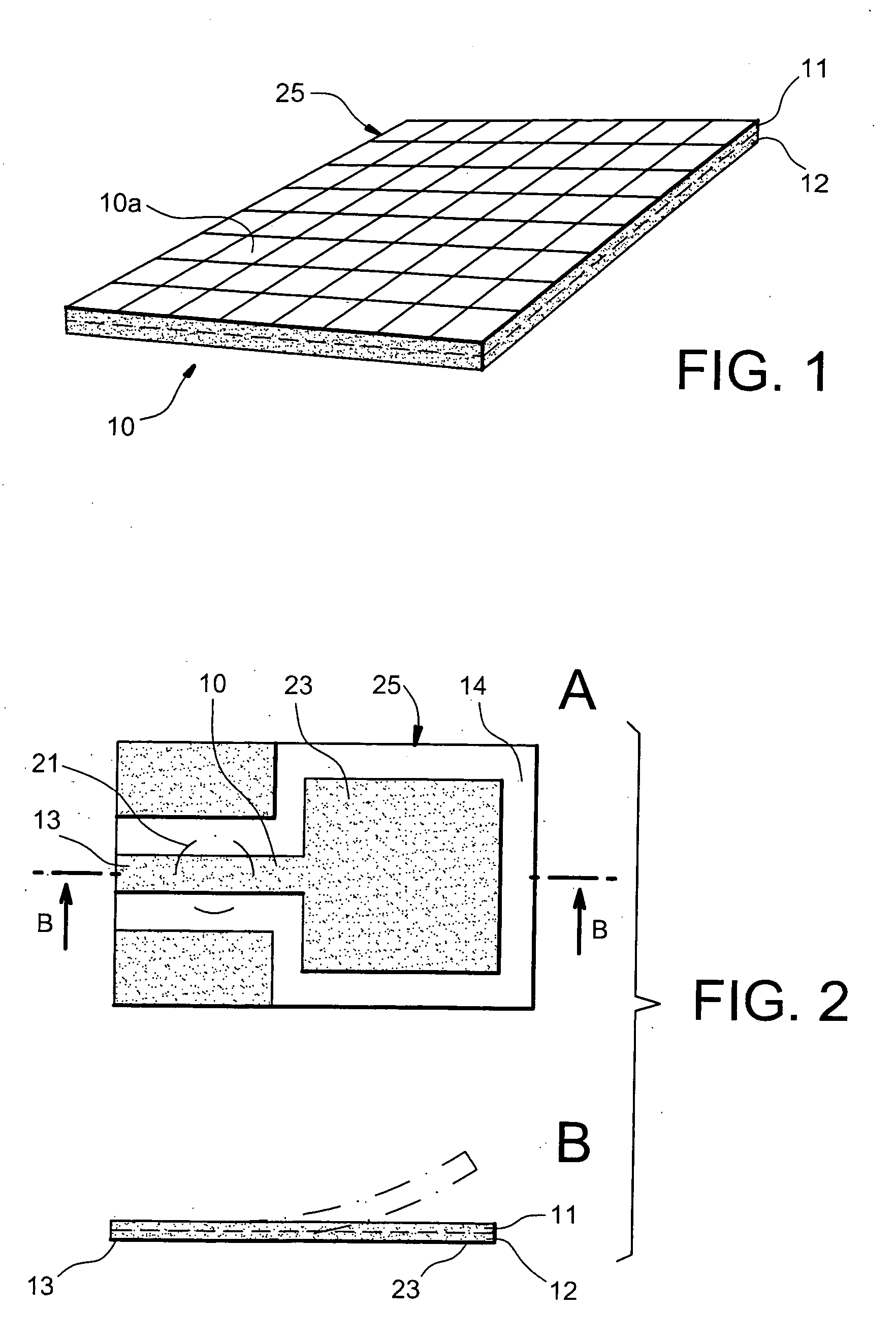
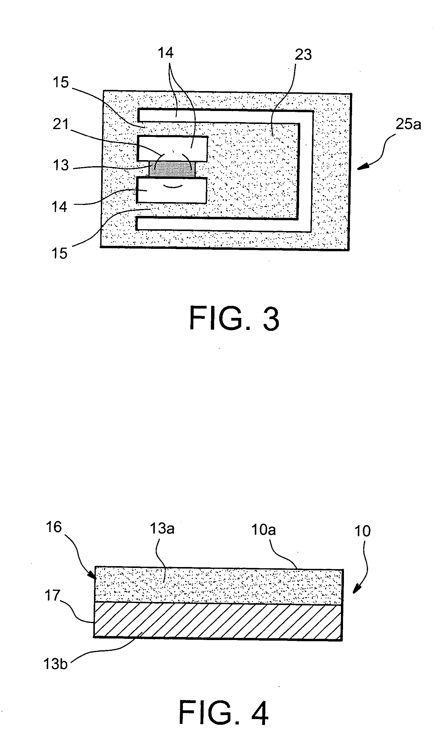
[0056] shown in FIG. 5 part A, the plate 10 is formed by two sub-plates 16, 19 assembled on one another for example by welding or bonding so as to form only a single plate 10. In the preferred form of this embodiment, the two sub-plates 16, 19 are adherent one to the upper face and the other to the lower face of an intermediate layer 18 made of a thermally insulating material. A first sub-plate 16 is made of a shape memory material A. A sub-plate 19 is made of a second shape memory material C having a memorised form different from the memorised form of the first. An exemplary embodiment of a modification element 25 is shown in a plan view in FIG. 5, part B. In this view, only a part 25a of the element 25 made in the upper sub-plate 16 is apparent. A blade 23a is obtained in the sub-plate 16 by means of two recesses 14, a first 14 having a U shape surrounding the blade 23a on three of its sides, and a second 14a having a form of a circle located substantially to the side of the open...

first embodiment

[0062]FIG. 6 shows a an exploded perspective view of a device comprising a tactile interface in the form of a plate 10 according to the present invention, in which control means 40 comprise laser means 42.

[0063] The display device 1 comprises a touch plate 10, as described hereinabove in relation to FIG. 1. The touch plate can also in this case be a plate made of heat-conductive material, in the form of a continuum. In this instance, even though the modification elements of the tactile sensation cannot be distinguished physically, elements do exist all the same. They are determined at each instant, for example in the form of pixels, by the position of the radiation laser on the surface. The size of the pixels here is determined by the size of the minimum surface which is heated by a radiation laser applied to a surface of the plate situated for example opposite the touch surface 10a, without any visual distinction of a delimitation of these elements being possible. The modification ...

second embodiment

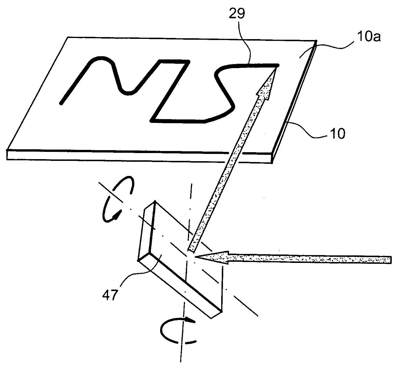
[0069]FIG. 7 shows an exploded perspective view of a device comprising a tactile interface in the form of a plate 10 according to the present invention, in which control means 40 comprise laser means 42. In reference to FIG. 6, the translation table 43 has been replaced by mobile mirror 47 mobile according to two perpendicular axes. The laser emitter 42 emits its radiation directly by means of a fibre optic, not shown here, to the mobile mirror 47. The control circuit 41 receiving the tactile data to be displayed, controls by way of position changing means 48, 49 the position in rotation of the mirror 47. Such rotation means of a reflector are known per se.

[0070] The operation is the same as in the example shown in FIG. 6, with the radiation shift being in this case produced by rotation controlled by the mirror 47.

[0071]FIG. 8 shows an exploded perspective view of a third embodiment of a device comprising a tactile interface in the form of a plate 10 according to the present invent...


PUM


Abstract

A device (1) comprising a tactile interface in the form of a plate (10) comprising an array of elements (25) enabling a surface (10a) of the plate (10) to be modified in a controlled manner, characterised in that the plate (10) is made of a shape memory material, and in that each element (25) is made up of an array of blades (23) solid with the plate (10) by an arm (13) solid monolithically with the plate (10) and the blade, a recess (14) of freedom of blade being present around the blade (23), the blade (23) having a first position at a first temperature and a second position at a second temperature.

Description

TECHNICAL FIELD [0001] The invention applies to the field of devices for transmitting tactile information to a user. It relates more particularly to a device comprising a tactile interface formed by a plate having a surface to be modified in a controlled manner, the plate comprising an array of elements for modification of the surface. [0002] Such plates are especially employed in touch plates or tactile interfaces for communicating information for example in the field of cars or in communicating objects, for example portable telephones or computer mice or in the field of objects for blind people. [0003] The invention applies also to the field of virtual reality, for example for reproducing the sensation of a texture. PRIOR ART [0004] U.S. Pat. No. 6,159,013 describes a portable optic sensor for blind people. The device comprises a touch plate fitted with holes in which surface element modification of the plate constituted in this case by rods are mobile. The position of the rods is...

Claims


Application Information

Patent Timeline
Patent Type & Authority Applications(United States)
IPC IPC(8): G09B21/00
CPCG09B21/003G09B21/00
Inventor HAFEZ, MOUSTAPHAALEXANDRE, JEAN-MARC
Owner COMMISSARIAT A LENERGIE ATOMIQUE ET AUX ENERGIES ALTERNATIVES
Why Eureka
Try Eureka