Cassette relay block attachment structure

a cassette relay and cassette technology, applied in the direction of vehicle components, electrical/fluid circuits, coupling device connections, etc., can solve the problems of many manufacturing costs, long manufacturing delivery time, and large box body achieve convenient attachment and detachment of cassette relay blocks, ensure lock power, and facilitate lock release

Active Publication Date: 2006-07-13
YAZAKI CORP
View PDF13 Cites 20 Cited by
  • Summary
  • Abstract
  • Description
  • Claims
  • Application Information

AI Technical Summary

Benefits of technology

[0030] According to the fourth aspect of the invention, the sure lock power is obtained with one touch by using the flexible lock arm, and lock release is easy. Therefore, attachment and detachment works of the cassette relay block are facilitated, and attachment work property and maintenance property of the electric connection box improve.
[0031] According to the fifth aspect of the invention, by the slide fitting between the rib and the guide groove, the tilt and rattling of the cassette relay block in the insertion into the peripheral walls are performed, so that the insertion is performed smoothly and surely. Therefore, the attachment work property of the cassette relay block improves, and wear and unusual sound due to vibration after the attachment to a vehicle are prevented.
[0032] According to the sixth aspect of the invention, without using the housing hole or space of the connection box body as the attaching side, the housing hole or space is provided into the cassette frame. Therefore, for example, by coupling the plural assemblies of which each comprises ...

Problems solved by technology

Therefore, since the large lock space is required, there is a problem that the cassette relay block and the connection box body for housing the cassette relay block are made large.
Further, since the connection box body...

Method used


Image

  • Cassette relay block attachment structure
  • Cassette relay block attachment structure
  • Cassette relay block attachment structure

Examples


Embodiment Construction

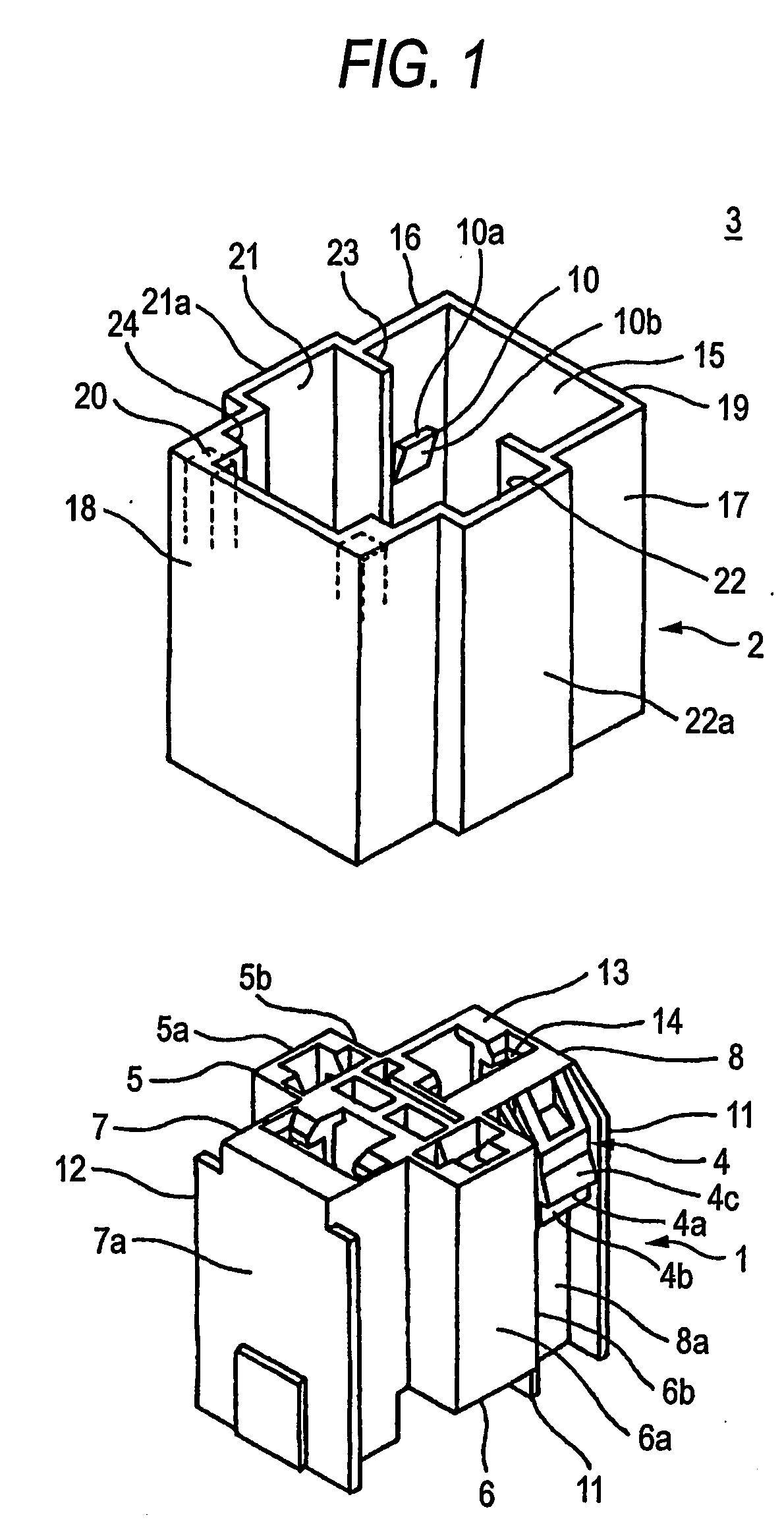
[0048]FIG. 1 shows one embodiment of cassette relay block attachment structure according to the invention.

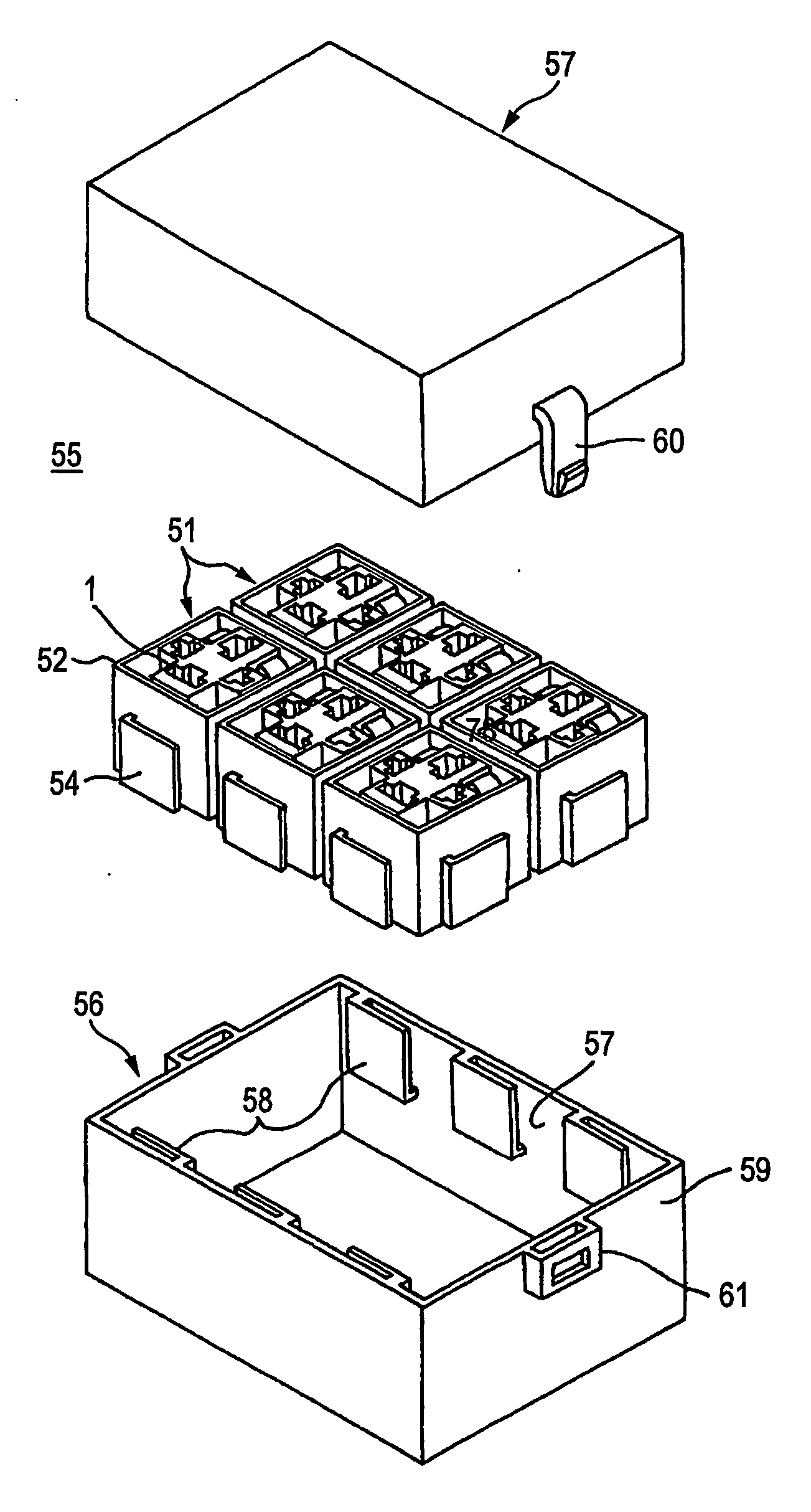
[0049] In this cassette relay block attachment structure, a single-pole cassette relay block 1 is fixed in a rectangular cassette frame (attaching side) 2 by a lock arm (lock portion) 4. The cassette relay block 1 and the cassette frame 2 constitute a relay block assembly 3.

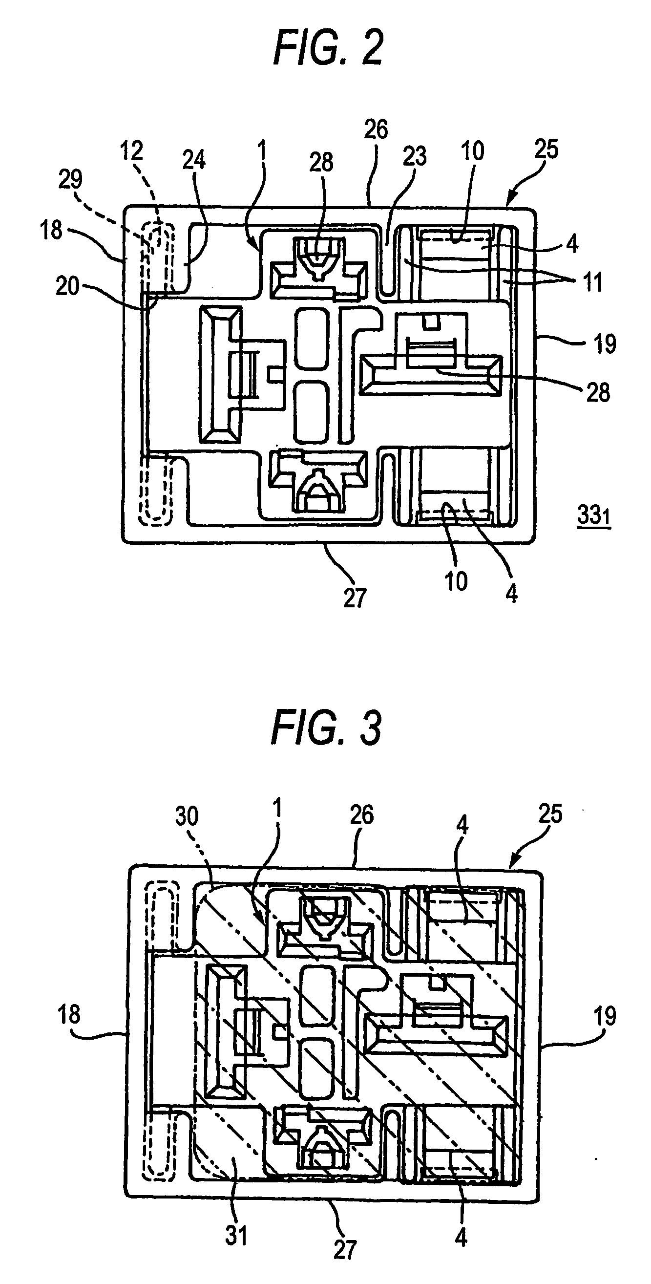
[0050] The cassette relay block 1 made of insulating resin has terminal housing parts 5 to 8 which protrude crosswise in four directions, that is, in front and rear, and left and right. On front and rear outer walls of either (herein, terminal housing part 8) of the left and right terminal housing parts 7, 8, a pair of flexible lock arms 4 are provided protrusively. The respective lock arms 4 are located more inside than outermost front and rear wall surfaces 5a and 6a of the front and rear terminal housing parts 5 and 6 (without protruding outward in the front and rear directions from the front and rear ou...


PUM


Abstract

Lock portions 4 are provided more inside than outer-most wall surfaces 5a, 6a of a cassette relayblock 1, and the cassette relay block 1 is inserted into space surrounded by periopheral walls 16 to 19 on an attaching side, and fixed by the lock portions 4 and locked portions 10 located on the peripheral wall side. The peripheral walls 16 to 19 on the attaching side are formed as a cassette frame 2. The cassette frame is used in common for the cassette relayblock 1 or other cassette electric parts mounting blocks. The plural cassette frames are coupled to each other by lock members 54, and coupled to a connection box body by locked members thereby to constitute an electric connection box.

Description

TECHNICAL FIELD [0001] The present invention relates to cassette relay block attachment structure in which a relay block in an automobile can be attached into an electric connection box in cassette form. BACKGROUND ART [0002] FIGS. 10(A) and (B) show one example of an electric connection box having the conventional cassette relay block attachment structure, for example, as shown in Unexamined Japanese Patent Publication 2003-125516. [0003] This cassette relay block 72, as shown in an enlarged view shown in a circle in FIG. 10 (B), is formed of insulation resin and nearly in the shape of a rectangular parallelepiped externally, and has plural terminal housing rooms 74 for inserting and fixing female terminals 73 (FIG. 11) from the downside in its required positions; and lock arms 75 for a connection box body 79 are provided respectively on outer wall surfaces on both sides of the cassette relay block 72. The terminal housing room 74 continues to a relay terminal insertion hole locate...

Claims


Application Information

Patent Timeline
IPC IPC(8): H01R13/502B60R16/02H01H45/04B60R16/023H02G3/16
CPCB60R16/0239
Inventor YAMADA, HIROAKIKANEKO, NOBUTAKAKANO, HIROAKISUZUURA, KATSUJI
Owner YAZAKI CORP
Why Eureka
Try Eureka