Releasably locking hinge for an orthopedic brace having adjustable rotation limits

a technology of rotation limit and hinge, which is applied in the field of hinges for orthopedic braces, can solve the problems of inherently increasing the risk of erroneously resetting the rotation limit, screw misplacement or loss, and the task of adjusting the rotation range of the hinge, and can require a significant degree of dexterity

Active Publication Date: 2006-07-13
BREG
View PDF35 Cites 52 Cited by
  • Summary
  • Abstract
  • Description
  • Claims
  • Application Information

AI Technical Summary

Benefits of technology

[0015] The rotation limiting mechanism includes a series of rotation limiting teeth formed in the first external inner face at the first external peripheral edge, a rotation limiting face formed in the internal peripheral edge, and a rotation limiting assembly. The rotation limiting assembly has an engagement face selectively positionable between two adjacent teeth of the series of teeth to place the rotation limiting assembly in a fixed position. The rotation limiting assembly also has a stop face engageable with the rotation limiting face upon rotation of the internal rotation plate relative to the first external rotation plate in a first rotation direction which substantially limits further rotation of the internal rotation plate relative to the first external rotation plate in the first rotation direction.

Problems solved by technology

However, It has been found that the task of adjusting the hinge rotation range can require a significant degree of dexterity to maneuver the relatively small screws into and out of the threaded holes.
Furthermore, the screws are susceptible to being misplaced or lost during this task.
Nevertheless, De Camp still requires the user to pry the leaf spring away from the hinge body and remove the pin from the hole when adjusting the hinge rotation range.
This sequence of steps inherently increases the risk of erroneously resetting the hinge rotation limit when the rotation limiting assembly is returned to the rotation limiting position if the user has forgotten or improperly locates the prior prescribed hinge rotation limit.

Method used


Image

  • Releasably locking hinge for an orthopedic brace having adjustable rotation limits
  • Releasably locking hinge for an orthopedic brace having adjustable rotation limits
  • Releasably locking hinge for an orthopedic brace having adjustable rotation limits

Examples


Embodiment Construction

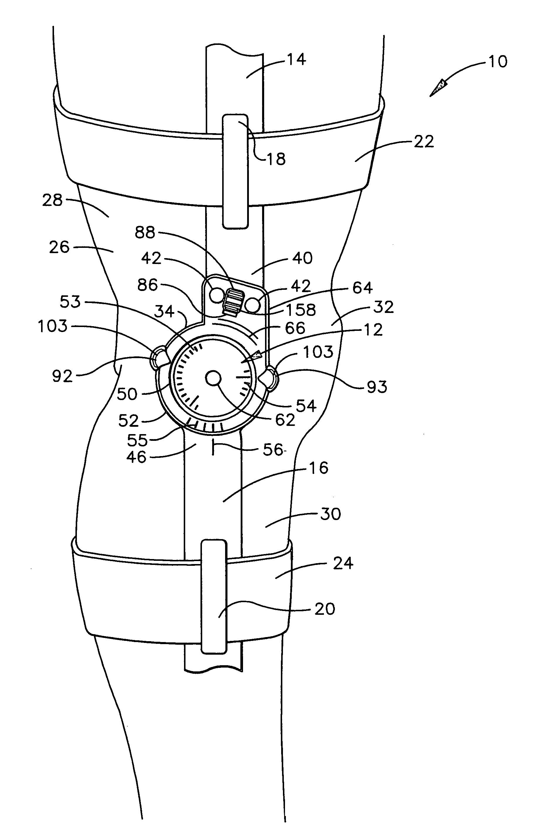
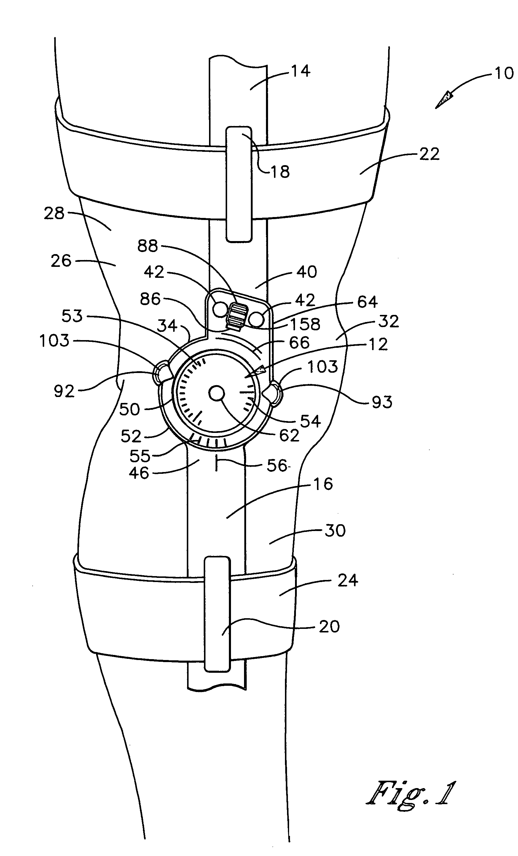
[0038] Referring initially to FIG. 1, a hinged orthopedic brace is shown and generally designated 10. There are a number of relative terms defined below which are used in the following description to distinguish various elements of the brace 10 from one another, but which are not to be construed as limiting the scope of the invention.

[0039] The relative terms “medial” and “lateral” characterize certain elements of the brace 10, which are positioned about the axis of rotation of the brace 10. The terms describe the relative proximity of the given element to the central longitudinal axis of the body of the user when the brace 10 is mounted thereon. In particular, a “medial” element is closer to the central longitudinal axis of the body, while a “lateral” element is further from the central longitudinal axis of the body.

[0040] The relative terms “inner” and “outer” likewise characterize certain elements of the brace 10, which are positioned about the axis of rotation of the brace 10....


PUM


Abstract

A hinge is provided for an orthopedic brace having a first rotation plate, a second rotation plate, a pivotal connector connecting the first and second rotation plates, a rotation limiting mechanism, and a rotation locking mechanism. The rotation limiting mechanism includes a rotation limiting face formed in the peripheral edge of the second rotation plate and a rotation limiting assembly selectively positionable in a fixed position relative to the first rotation plate. The rotation limiting assembly has a stop face engageable with the rotation limiting face upon rotation of the first and second rotation plates, which limits further rotation in a first rotation direction. The rotation locking mechanism includes a rotation lock pin and a series of lock notches formed in the peripheral edge of the second rotation plate. The rotation lock pin is selectively positionable within one of the series of lock notches, which substantially locks the first and second rotation plates against rotation in the first rotation direction or in a second rotation direction opposite the first.

Description

TECHNICAL FIELD [0001] The present invention relates generally to orthopedic braces, and more particularly to a hinge for an orthopedic brace, wherein the hinge has a mechanism for selectively adjusting the range of hinge rotation and a mechanism for releasably locking the hinge in a fixed position without altering the selected hinge rotation limits. BACKGROUND OF THE INVENTION [0002] Hinges for orthopedic braces having an adjustable rotation range in the extension and flexion direction are well known in the art. For example, U.S. Pat. No. 4,481,941 to Rolfes discloses a hinge having a pair of threaded screws, each being selectively threadably securable in one of a plurality of correspondingly threaded holes formed in the body of the hinge. The hinge rotation range is a function of screw placement insofar as securing a screw in a given hole determines a particular hinge rotation limit. The hinge rotation range is adjusted by changing the hinge rotation limit, which requires removal ...

Claims


Application Information

Patent Timeline
Patent Type & Authority Applications(United States)
IPC IPC(8): A61F5/00
CPCA61F5/0125A61F2005/0139A61F2005/0158A61F2005/0167
Inventor MASON, JEFFREY T.ODDOU, PAUL
Owner BREG
Why Eureka
Try Eureka