Bottom fish rigs with fish hooks

a technology of fish hooks and bottom fish rigs, which is applied in the field of bottom fish rigs with fish hooks, can solve the problems of affecting the quality of fish rigs, the hooks' barbs could actually be pointing downward, and the hooks could be snagged on objects, and disadvantages, etc., and achieves low manufacturing cost and low price of sale , easy and efficient manufacturing and marketing

Inactive Publication Date: 2006-07-20
BRZOZOWSKI FR T
View PDF9 Cites 21 Cited by
  • Summary
  • Abstract
  • Description
  • Claims
  • Application Information

AI Technical Summary

Benefits of technology

[0035] It is therefore an object of the present embodiment of the invention to provide a new and improved horizontal unilateral fish hook that has all of the advantages of the prior art fishing tackle and none of the disadvantages.
[0036] It is another object of the present embodiment of the invention to provide a new and improved bottom fish rigs with fish hooks that may be easily and efficiently manufactured and marketed.
[0037] An even further object of the present embodiment of the invention is to provide a new and improved horizontal unilateral fish hook that has a low cost of manufacture with regard to both materials and labor, and which accordingly is then susceptible of low prices of sale to the consuming public, thereby making such bottom fish rigs with fish hooks economically available to the buying public.
[0038] Still another object of the present embodiment of the invention is to provide a new bottom fish rigs with fish hooks that provides in the apparatuses and methods of the prior art, some of the advantages thereof, while simultaneously overcoming some of the disadvantages normally associated therewith.
[0039] Another object of the present embodiment of the bottom fish rigs with fish hooks is its novel features, consisting of attributes that most other fishing hooks do not possess; it has loops that close and resists snagging by preventing objects from sticking in the loops.
[0040] Another object of the present embodiment of the bottom fish rigs with fish hooks is to be fairly compact and to have small loops on wire leaders, and preset open loops that are able to close upon using leaders of monofilament fishing line.

Problems solved by technology

When the fishing line is jerked, the force toward the eye causes a horizontal unilateral fish hook to flip upright; however, when baited, the VMC, Gamakatsu® frog hook and similar double hooks become top heavy land on the bottom of waterways upside down; their barbs could snag onto objects.
A disadvantage of the Shriver patent, the Mustad® Double Live Bait Hook and the Gamakatsu® frog hook is that once bait is inserted upon the hooks, the combination could become top-heavy and the barbs of the hooks could actually be pointing downward and become snagged onto objects.
This disadvantage might also occur to the Automatic fishhook by Lemons, U.S. Pat. No. 6,497,068 which is a one piece double hook that has two legs that have barbs connected to a torsion spring that resembles a spring with 2 fishing hooks on the ends; Lemons' patent does not resemble the fishing hooks in stores nor does it resemble a horizontal unilateral fish hook.
However, the Carlson '178 patent has a different mechanical function and is unlike a horizontal unilateral fish hook that resists snagging.
However, the Lewis '910 patent does not have a horizontal unilateral fish hook that resists snagging.
However, the Snyder '508 patent does not have a horizontal unilateral hook that resists snagging.
However, the Levin '660 patent does not have a horizontal unilateral fish hook that resists snagging.

Method used


Image

  • Bottom fish rigs with fish hooks
  • Bottom fish rigs with fish hooks
  • Bottom fish rigs with fish hooks

Examples


first embodiment

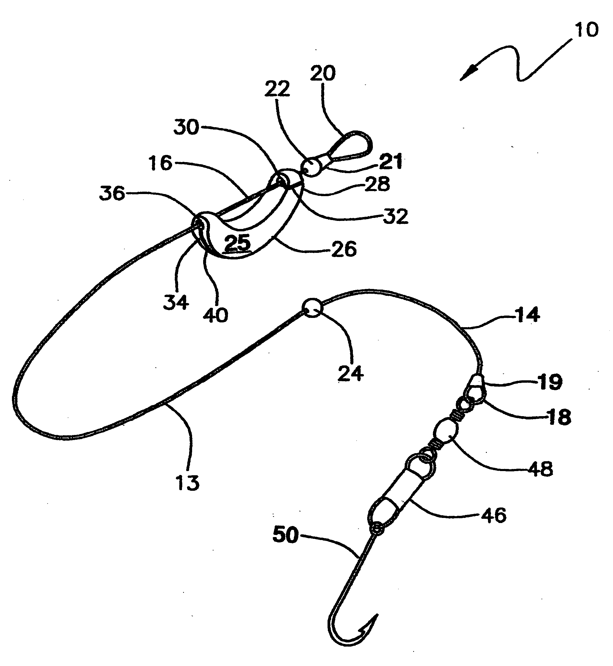
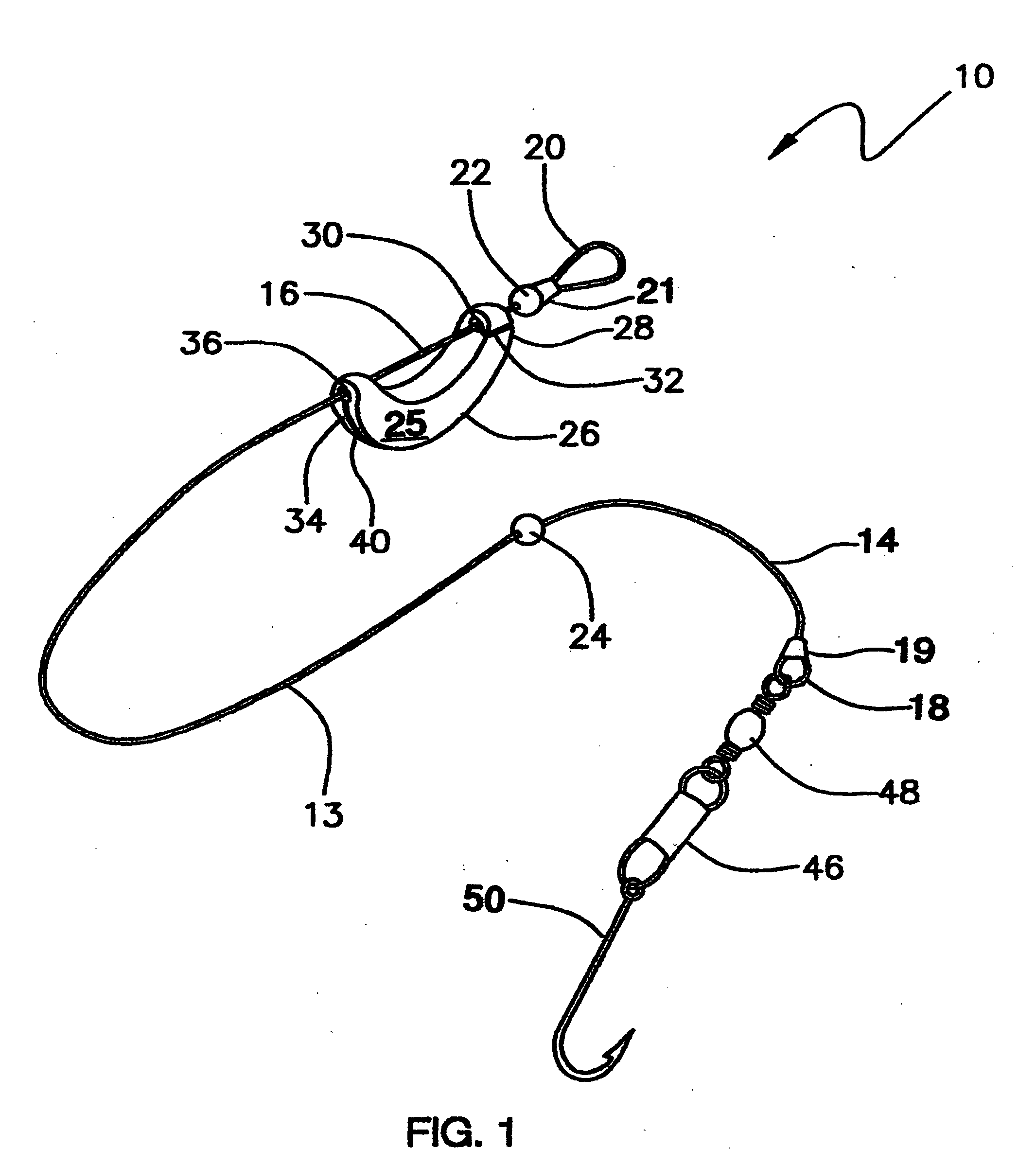
[0058] the present invention FIG. 1 has a new and improved bottom fish rig with fish hook 10 for fishing tackle with a removable sliding c-weight 25 and as a fish hooking means, a single hook 50 that is illustrated and will be described. More particularly, a bottom fish rig with a fish hook 50 has an elongated leader 13 that has two opposite ends, a leader hook end 14 and a leader line end 16. A leader hook end 14 has a leader hook loop 18 that is held securely by a crimped hook loop lug 19 therein: said metallic lugs are crimped over 2 wire strands forming a loop. A leader line end 16 has a leader line loop 20 that is attached to the fishing line from a fishing rod. A line end 16 has a leader line loop 20 that is held securely by a crimped line loop lug 21 therein. A first movement stop 22 is frictionally connected to said leader 13 adjacent said leader line end 16, said first movement stop 22 is comprised of means of obstructing any passage beyond that point with a fixed object su...

second embodiment

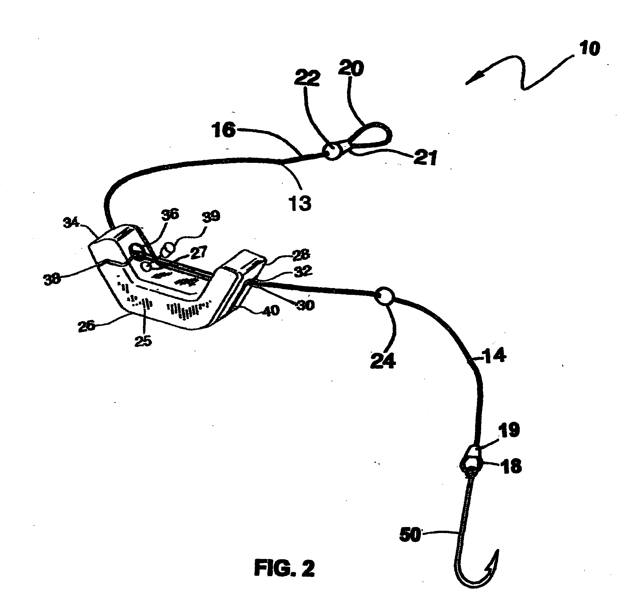
[0062]FIG. 2 is the second embodiment which has an elongated leader 13 having two opposite ends, a leader hook end 14 and a leader line end 16, said hook end having a leader hook loop 18 secured by a metallic leader hook loop lug 19 therein, said leader line end having a leader line loop secured by a leader line loop lug 19, metallic lugs are crimped and fixably attached to a wire leader therein, said metallic lugs are crimped over 2 wire strands forming a loop. A first movement stop 22 is frictionally connected to said leader adjacent said line end, said first movement stop is comprised of means of obstructing any passage beyond that point with a fixed object such as a crimped split shot, said first movement stop 22 is inserted near the leader line loop lug 21. A second movement stop 24 frictionally connected to said leader 13, said second movement stop 24 located between said first movement stop 22 and said leader hook end 14, said second movement stop 24 is comprised of a means o...

third embodiment

[0065] The third embodiment FIG. 3 has an elongated leader 13 constructed from monofilament fishing line. The elongated leader 13 has two opposite ends; an elongated leader having a leader hook end 14 that has a leader hook loop knot 15 and a leader line end 16 has a leader line loop 20. A leader hook loop knot 15 consists of a means of closing the loop around the fish hook 50. An elongated leader having a leader hook loop knot 15 is attached to a fish hook 50. A fish hooking means includes a single hook 50, a double hook, a treble hook or a horizontal unilateral fish hook with 2 or 3 horizontal prongs.

[0066] In FIG. 3 a leader line end 16 has a leader line loop 20 secured by a leader line loop knot 17 therein; a leader line loop knot 17 having leader line loop 20 that is opened yet having a means of closing the loop 20 to prevent objects from being caught therein; a leader line loop 20 created by a slip-knot means including a hangman's knot, scaffold knot, gallows knot, strangle kn...


PUM


Abstract

The bottom fish rig with fish hooks 10 has a sinker attachment means of securing weight upon a leader 13 with small wire loops 18 and 20 and a fish hooking means. An elongated leader 13 has a hook end 14 and a line end 16. The hook end 14 has a leader hook loop 18 and fish hook 50. The leader line end 16 has a leader line loop 20. A first movement stop 22 is crimped to the leader 13 before the leader line loop 20. A second movement stop 24 is crimped to the leader about two-thirds of the length. A sliding c-weight 25 connects to the leader 13 between movement stops.

Description

CROSS REFERENCE TO RELATED APPLICATIONS [0001]Country -NumberMM-YYYYName ClassificationU.S. Patent DocumentsU.S. Patent No. 6,770,29508-2004Davidson, Lawrence P. 43 / 43.16U.S. Patent No. 6,739,08505-2004Burczynski, Michael J. 43 / 43.16 43 / 43.4U.S. Patent No. 6,691,44902-2004Hoben, Donald M 43 / 43.16, 434 / 43.2U.S. Patent No. 6,655,07512-2003Bohn, Greg 43 / 43.6U.S. Patent No. 6,640,48911-2003Rigney, Jan J. 43 / 42.37U.S. Patent No. 6,560,91705-3002Van Der Hoven, et al 43 / 43.4, 43 / 43.16, 43 / 37U.S. Patent No. 6,526,69003-2003Dillard, Michael C. 43 / 4, 269 / 907U.S. Patent No. 6,519,89502-2003Bennett, Thomas J. 43 / 44.81 43 / 42.39, 43 / 43.16U.S. Patent No. 6,497,068B112-2002Lemons, John D. 43 / 36U.S. Patent No. 6,325,13612-2001Ratte, Geoffrey S. 164 / 129, 164 / 131U.S. Patent No. 6,305,12111-2000Adams, Nicholas S. 43 / 44.96, 43 / 43.1U.S. Patent No. 6,170,19101-2001Laney, Scot H. 43 / 43.13 43 / 44.9U.S. Patent No. 6,145,24006-1999Adams, Nicholas S. 43 / 44.96U.S. Patent No. 6,076,29706-2000Lippincott, Robert 43...

Claims


Application Information

Patent Timeline
Patent Type & Authority Applications(United States)
IPC IPC(8): A01K91/00
CPCA01K91/04A01K91/06A01K91/14A01K95/02
Inventor BRZOZOWSKI, FRANK T.
Owner BRZOZOWSKI FR T
Why Eureka
Try Eureka