Apparatus and method for dispensing discrete amounts of viscous material

a technology of viscous material and apparatus, which is applied in the direction of liquid transfer devices, lighting and heating apparatus, domestic cooling apparatus, etc., can solve the problems of difficult cleaning, time-consuming and laborious replacement and cleaning in conventional non-contact dispensing apparatus, and high viscous material that cannot easily flow under their own weight at room temperatur

Inactive Publication Date: 2006-07-20
NORDSON CORP
View PDF41 Cites 83 Cited by
  • Summary
  • Abstract
  • Description
  • Claims
  • Application Information

AI Technical Summary

Benefits of technology

[0015] In yet another embodiment of the invention, a nozzle assembly includes a dispensing body with a discharge passageway positioned to receive a flow of a viscous material from a dispensing apparatus. The discharge passageway has a discharge outlet from which the viscous material is discharged. The nozzle assembly further includes a heat transfer body removably attaching the dispensing body to the dispensing apparatus. The heat transfer body has a fluid passageway adapted to receive a flow of the coolant gas and positioned such that the flow of the coolant gas exiting the fluid passageway does not impinge the viscous material discharged from the discharge passageway.

Problems solved by technology

Generally, such highly viscous materials cannot easily flow under their own weight at room temperature.
Valve seat replacement and cleaning in conventional non-contact dispensing apparatus is a time consuming and painstaking process as the internal surfaces of the dispensing apparatus are difficult to access with cleaning tools.
Generally, the valve seat is integral with the fluid chamber and, as a result, is non-removable, which restricts access to the fluid chamber and creates a circular right angle corner at their juncture that is difficult to clean.
However, the guide vanes define right angle corners that are difficult to adequately clean effectively in a short time.
Disassembling and reassembling conventional non-contact dispensing apparatus is a difficult process that involves numerous tools.
As a result of the complexity, disassembly and reassembly are slowed and may take as long as forty-five (45) minutes to complete, even for technicians skilled in the assembly procedure.
Any attempt to replace the valve seat to, for example, change the diameter of the discharge passageway often results in leakage because the needle tip and the new valve seat are not a matched pair and, therefore, cannot provide an adequate seal.
Another problem encountered in conventional pneumatic non-contact dispensing apparatus is noise.

Method used


Image

  • Apparatus and method for dispensing discrete amounts of viscous material
  • Apparatus and method for dispensing discrete amounts of viscous material
  • Apparatus and method for dispensing discrete amounts of viscous material

Examples


Embodiment Construction

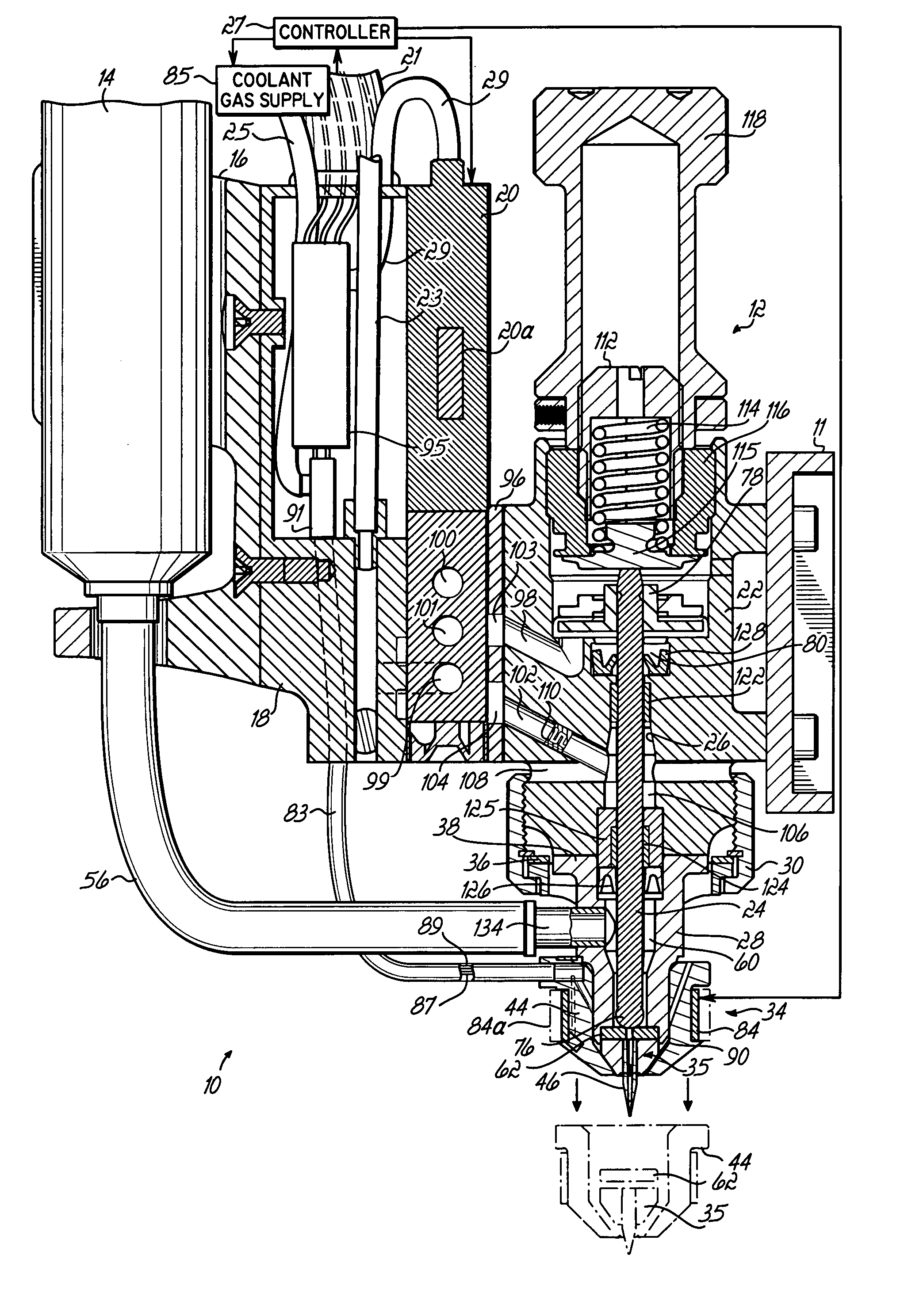
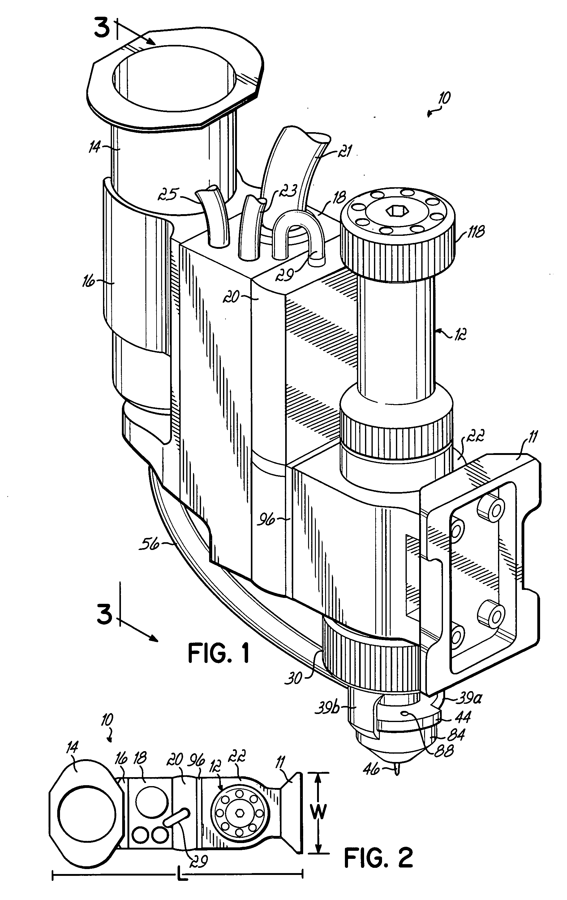
[0034] With reference to FIGS. 1 and 2, a dispensing apparatus 10 for use with a computer-controlled non-contact dispensing system (not shown) is shown. The dispensing apparatus 10 of the invention may be installed in dispensing systems including those similar, or identical to, the dispensing systems described in U.S. Pat. No. 5,747,102 entitled “Method and Apparatus for Dispensing Small Amounts of Liquid Material”, the disclosure of which is incorporated herein by reference in its entirety. Dispensing apparatus 10 is particularly useful when installed in the Asymtek X-1010 Axiom™ SMT Dispenser, the Asymtek X-1020 Axiom™ Semiconductor Dispenser, the Asymtek M-2020 Millennium® Ultra High Speed Semiconductor Dispenser, or the Asymtek M-2010 Millennium® Ultra High Speed SMT Dispenser. The dispensing apparatus 10 includes a mount 11, illustrated in FIGS. 1 and 2 as a dovetail mount, for attaching dispensing apparatus 10 to a mechanical support of the dispensing system.

[0035] The dispen...


PUM


Abstract

Apparatus and methods for dispensing small amounts of a viscous material onto a workpiece. The narrow-profile dispensing apparatus includes a fluid chamber, a nozzle, and a valve seat disk representing individual components that are removable from a main body of the dispensing apparatus for cleaning and/or replacement. The nozzle is coupled with the fluid chamber by a heat transfer body that may be cooled by, for example, a cooling fluid routed through an air pathway defined in the heat transfer body. The main body of the dispensing apparatus may be cooled by air exhausted from an air cavity of a pneumatic actuator regulating the movement of a needle to control the flow of viscous material in the dispensing apparatus.

Description

CROSS-REFERENCE TO RELATED APPLICATIONS [0001] This application is a continuation of Serial No. PCT / US2004 / 020247 filed on Jun. 25, 2004 which claims the benefit of U.S. Provisional Application No. 60 / 487,034 filed on Jul. 14, 2003, the disclosures of which are hereby incorporated by reference herein.FIELD OF THE INVENTION [0002] The present invention generally relates to dispensing apparatus and methods and, in particular, to apparatus and methods for dispensing discrete amounts of viscous materials in a non-contact manner onto a workpiece. BACKGROUND OF THE INVENTION [0003] In the manufacture of microelectronic hardware and other products, pneumatic dispensing apparatus are used to dispense small amounts or droplets of a highly viscous material in a non-contact manner onto a substrate or workpiece. Exemplary highly viscous materials include, but are not limited to, solder flux, solder paste, adhesives, solder mask, thermal compounds, oil, encapsulants, potting compounds, inks, and...

Claims


Application Information

Patent Timeline
Patent Type & Authority Applications(United States)
IPC IPC(8): B67D3/00B05CB05C5/00B05C5/02B05C11/10B67D7/08B67D7/80
CPCB05C5/001B05C5/0225H05K13/046B05C11/1034B05C5/0237B05C5/02B05B1/02
Inventor FISKE, ERIKQUINONES, HORATIOMAIORCA, PHILBABIARZ, ALECCIARDELLA, ROBERT
Owner NORDSON CORP
Why Eureka
Try Eureka