Wing, in particular airfoil of an aircraft, with a variable profile shape

Active Publication Date: 2006-07-20
AIRBUS OPERATIONS GMBH
View PDF11 Cites 59 Cited by
  • Summary
  • Abstract
  • Description
  • Claims
  • Application Information

AI Technical Summary

Benefits of technology

[0004] Amongst other things, it may be an object of the invention to create a wing, in particular a carryin

Problems solved by technology

By way of these, deflection of the flow on the wing is not optimal from the point of view of aerodynamics, and furthermore the load distribution

Method used


Image

  • Wing, in particular airfoil of an aircraft, with a variable profile shape
  • Wing, in particular airfoil of an aircraft, with a variable profile shape
  • Wing, in particular airfoil of an aircraft, with a variable profile shape

Examples


Embodiment Construction

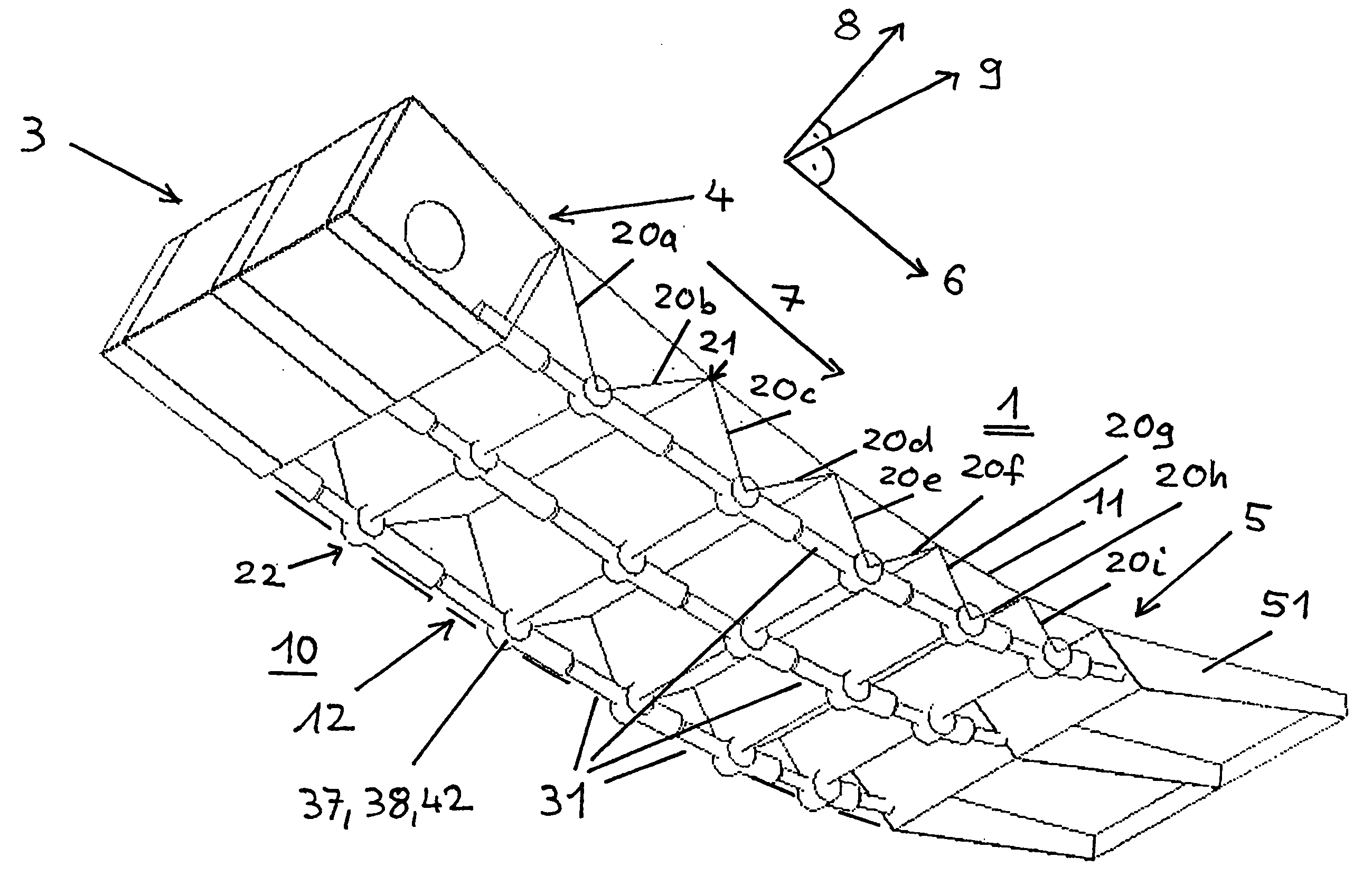
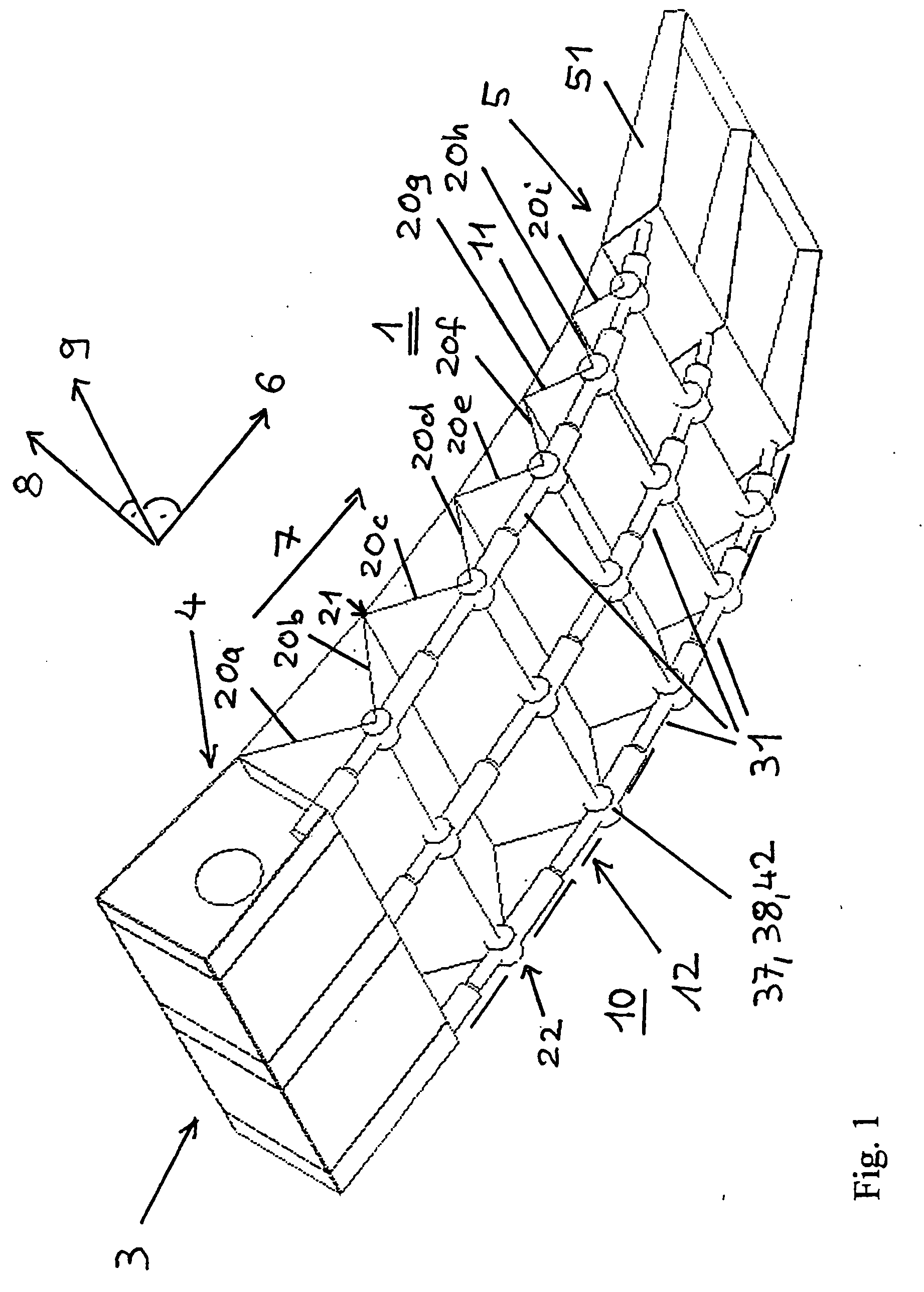
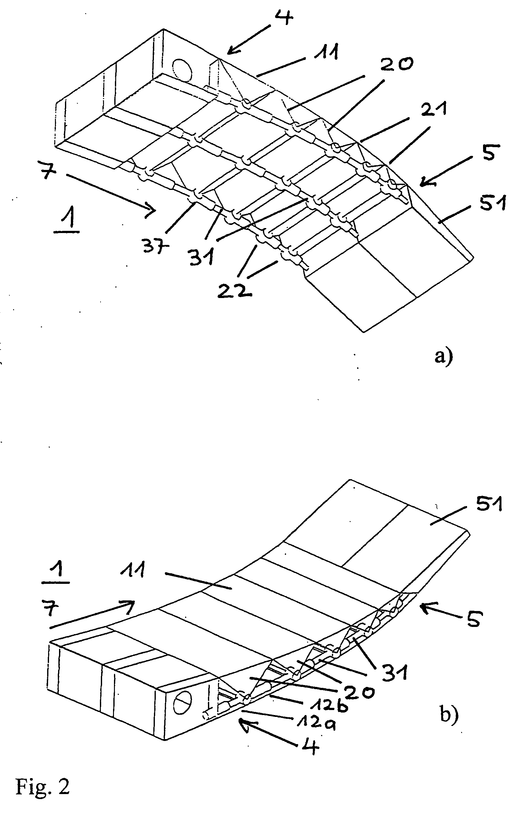
[0041] The airfoil 1 shown in FIGS. 1 to 5 comprises a first end 4 with an attachment position 3 that is intended for attaching the wing to a component or structural part of an aircraft, and a second end 5, which is a free end. The attachment position 3 is suitably fashioned, for example comprising an eyelet which is determined by means of a pin on the structural part of the aircraft. In the embodiment shown in the figures the first end 4 is provided as a front end when viewed in the direction of flow 6, while the second end 5 is provided as a rear end when viewed in the direction of flow 6. According to other embodiments, the wing 1 can however also be arranged in such a way that the second end 5 opposes the direction of flow 6.

[0042] The wing 1 can be a carrying airfoil, a rudder, an elevator or some other aerodynamically or hydrodynamically effective control surface. Its use is not limited to aircraft; the principles apply to all types of carrying surfaces and control surfaces t...


PUM


Abstract

A wing, in particular a airfoil of an aircraft, with a variable profile shape, which wing comprises a first skin and a second skin and a supporting structure, arranged between the first and the second skin, which supporting structure in the direction of the wing depth extends between a first end and a second end, wherein the form of said supporting structure, for the purpose of varying the profile shape by means of a drive device comprising drive elements, is variable. The supporting structure comprises ribs, arranged one behind the other in the direction of the wing depth, which ribs at connection positions are interconnected so as to be articulated, wherein said ribs at first connection positions are connected to the first skin, and at second connection positions are connected to the second skin. For the purpose of setting the variable profile the mutual spacing of the second connection positions can be varied by means of the drive elements.

Description

REFERENCE TO RELATED APPLICATION [0001] This application claims the benefit of the filing date of the German Patent Application No. 10 2004 062 998.6 filed Dec. 22, 2004, the disclosure of which is hereby incorporated herein by reference. FIELD OF THE INVENTION [0002] The invention relates to a wing, in particular a carrying airfoil of an aircraft, with a variable profile shape. TECHNOLOGICAL BACKGROUND [0003] Conventionally, control flaps that are used to vary the profile of a wing, in particular of the carrying airfoil of an aircraft, but also to vary the profile of rudders and elevators, are made as rigid wing components. By way of these, deflection of the flow on the wing is not optimal from the point of view of aerodynamics, and furthermore the load distribution is unfavourable because the linking of the control flap to individual attachment positions on the wing results in relatively large local stress. SUMMARY OF THE INVENTION [0004] Amongst other things, it may be an object ...

Claims


Application Information

Patent Timeline
IPC IPC(8): B64C3/44
CPCB64C3/48
Inventor VOGLSINGER, MARTINPEREZ-SANCHEZ, JUAN
Owner AIRBUS OPERATIONS GMBH
Why Eureka
Try Eureka