Catadioptric 1x projection system and method

a catadioptric and projection system technology, applied in the field of catadioptric projection system and method, can solve the problems of severe obscuration problems, low numerical apertures of prior systems, and relatively high residual aberrations

Inactive Publication Date: 2006-07-20
NIKON CORP
View PDF20 Cites 42 Cited by
  • Summary
  • Abstract
  • Description
  • Claims
  • Application Information

AI Technical Summary

Problems solved by technology

However, in the applicant's experience, such prior systems have been limited to low numerical apertures (N.A.'s) or small field sizes.
Moreover, they also suffer from relatively high residual aberrations, even at low NA's or field sizes, and tend to have severe obscuration problems as the NA or field sizes are increased.
Thus, it is believed unlikely that they can be applied successfully to large-field, sub-micron resolution applications.
However, such derivatives have had low NA's, which means that they cannot be used for large-field, sub-micron resolution, projection systems.

Method used


Image

  • Catadioptric 1x projection system and method
  • Catadioptric 1x projection system and method
  • Catadioptric 1x projection system and method

Examples


Embodiment Construction

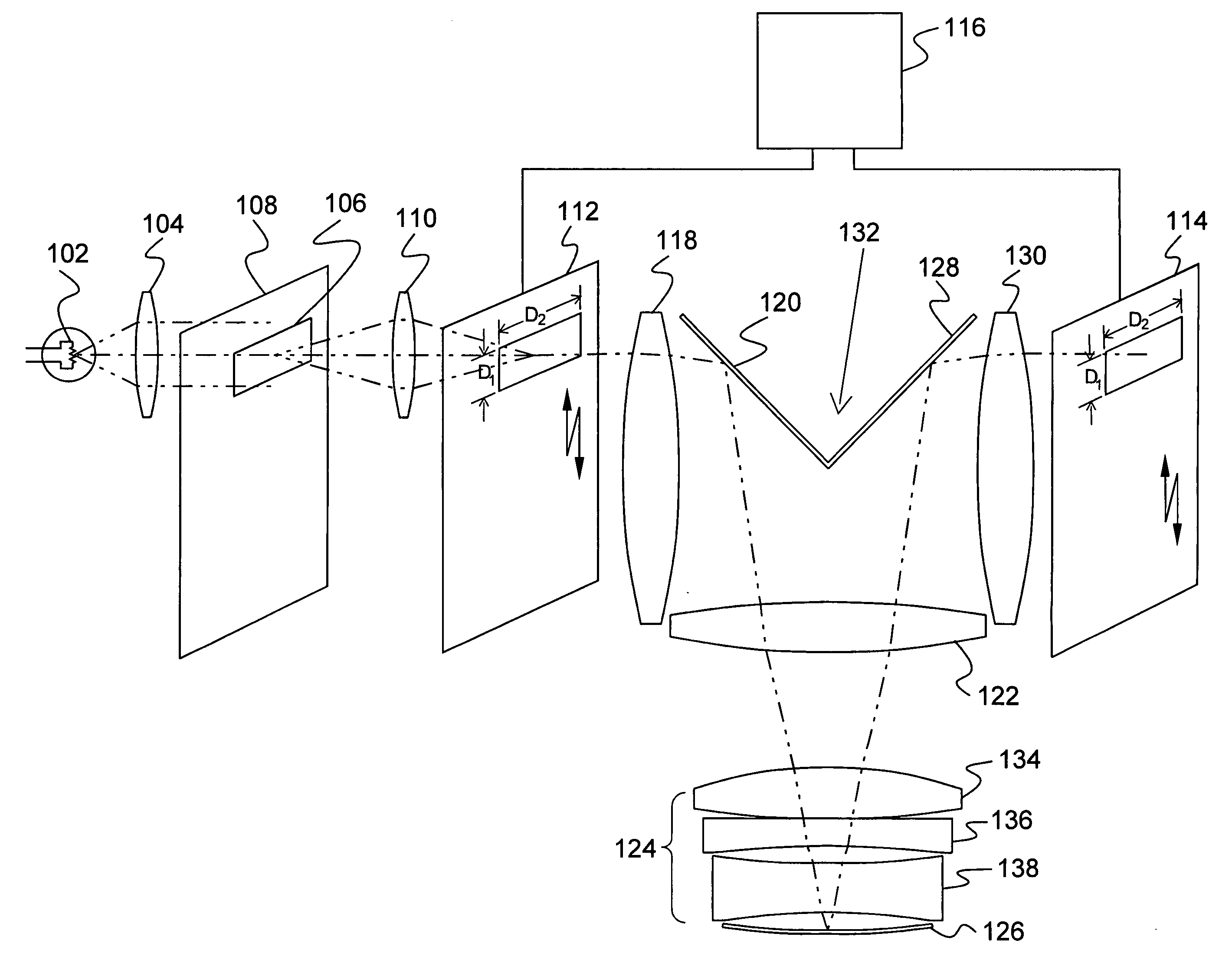
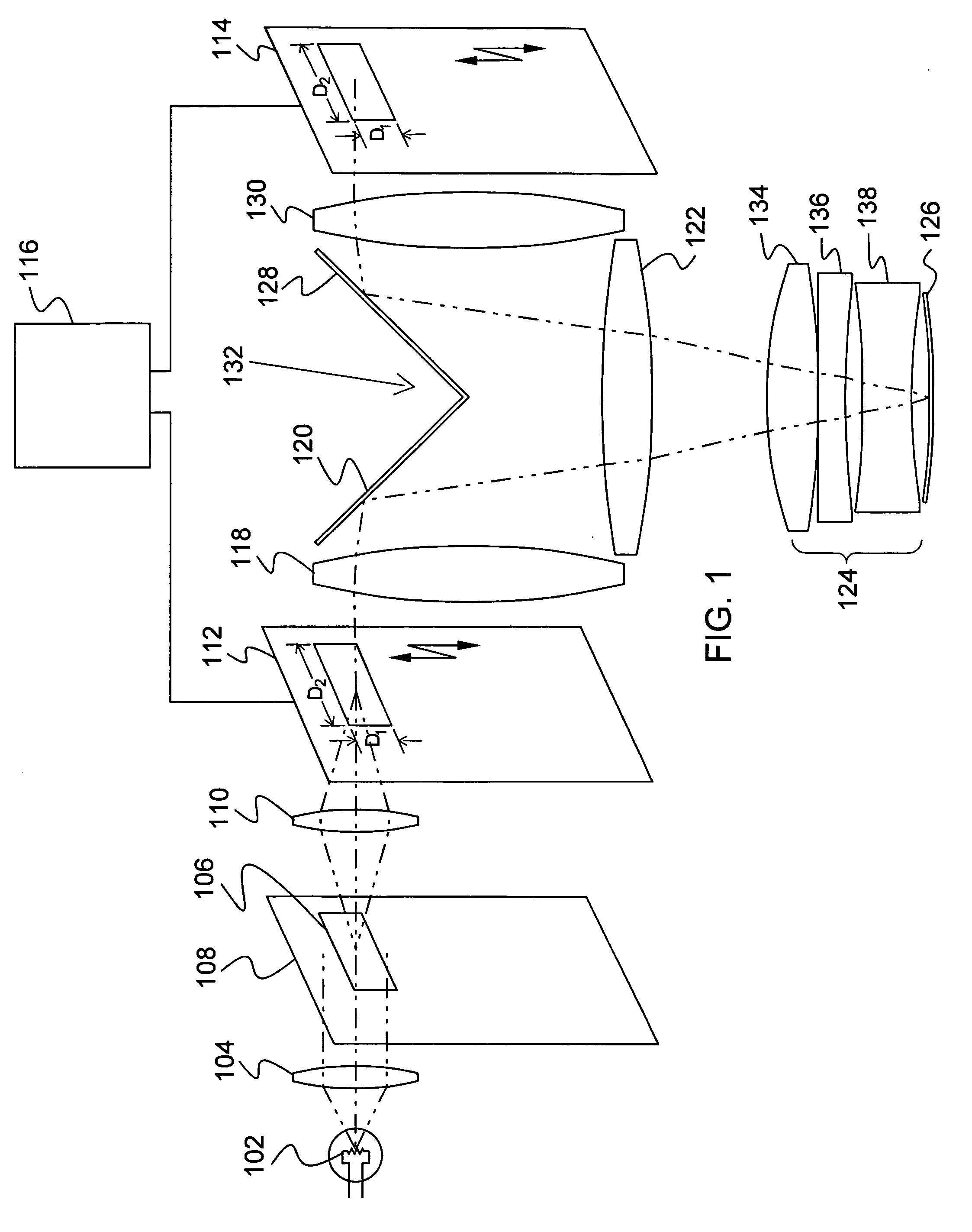
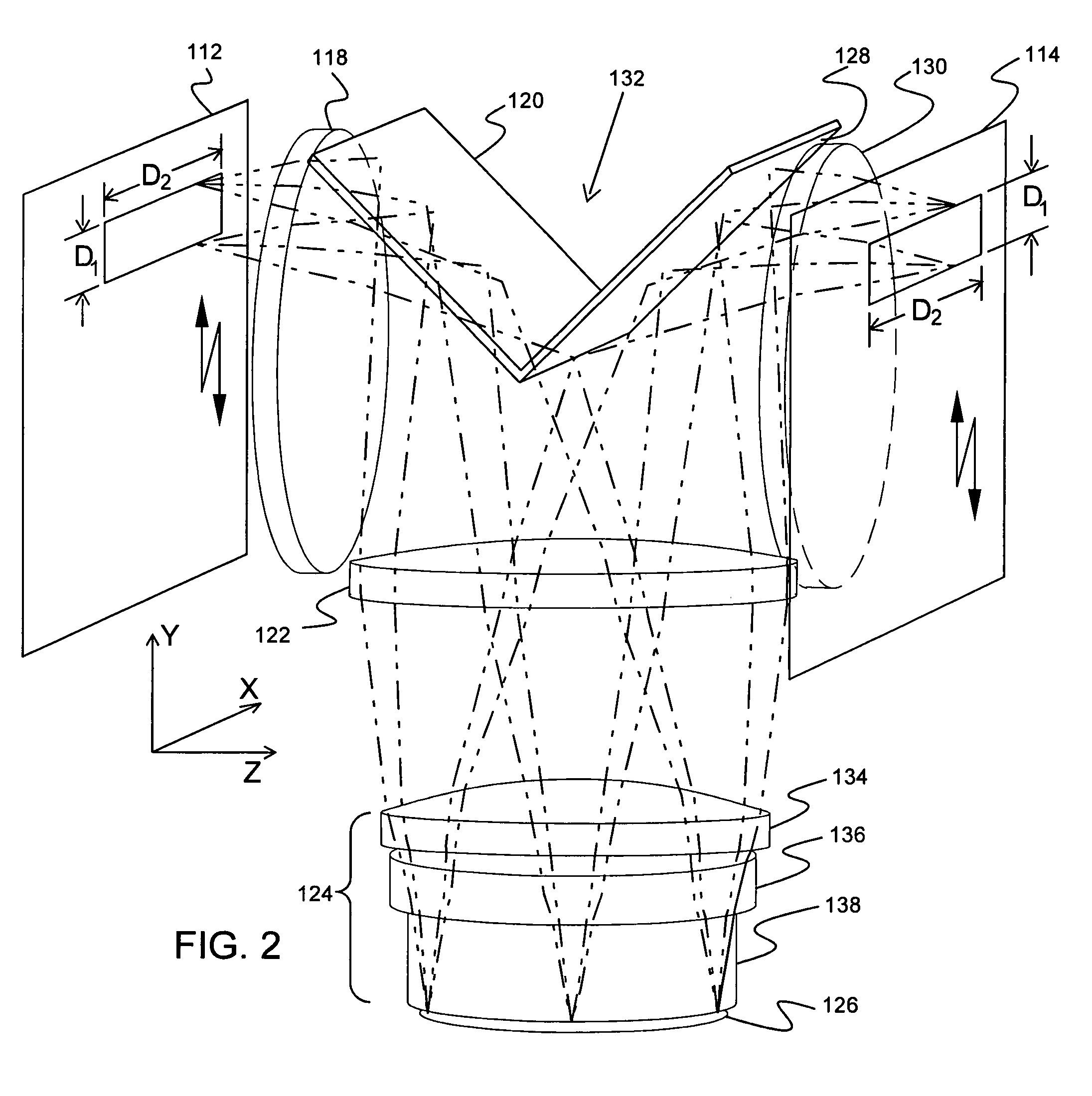
[0017]FIG. 1 illustrates one preferred embodiment of a catadioptric 1× projection system 100, according to the principles of the present invention. The system includes an illumination source 102, which according to the one embodiment emits light at the spectral bandwidth of the Mercury I line (365 nm). The light is collimated by a condenser lens 104, and directed through a rectangular aperture 106 in a diaphragm 108. A relay lens 110 projects an image of the rectangular diaphragm aperture 106 onto a mask 112, which forms an object plane of the system. The illumination optical system 104-110 may comprise an optical integrator for providing a uniform illumination distribution on the object plane and / or an image plane. The optical integrator can be a Fly's eye lenses and / or a Rod integrator. The rectangular diaphragm aperture of the diaphragm 108 can be modified to provide a trapezoidal diaphragm aperture, a hexagonal diaphragm aperture, or other polygonal diaphragm aperture. The proje...


PUM


Abstract

A new and useful method and projection system for projecting an image from an object plane to an image plane is provided. The method and system is designed to operate at a 1× magnification, a relatively high NA, with a relatively large instantaneous scanning field, and to achieve sub-micron resolution at high optical throughput. An object plane is scanned across an instantaneous rectangular field at least 40 mm in the direction of scan and at least 132 mm in a direction that is perpendicular to the scan, and the scanned image is projected onto the image plane through a catadioptric projection system configured for a 1× magnification and a numerical aperture of at least 0.23. The catadioptric projection system includes (i) a first field lens group configured to transmit an image ray bundle from the object plane, (ii) a first plane reflector configured to reflect and redirect the image ray bundle projected from the first field lens group, (iii) a second lens group in the optical path of the reflected, redirected image ray bundle, and a concave reflector following the second lens group, the concave reflector configured to reflect and return the reflected image ray bundle through the second lens group, (iv) a second plane reflector configured to reflect and redirect the returned image ray bundle, and (v) a third field lens group configured to receive and project the reflected, returned image ray bundle onto the image plane.

Description

BACKGROUND [0001] The present invention relates to a catadioptric projection system and method for projecting an image from an object plane to an image plane. [0002] A catadioptric projection system is a system that uses both refraction (e.g. one or more lens elements) and reflection (e.g. one or more mirrors) to project an image from an object plane to an image plane. Historically, catadioptric 1× projection lenses have been widely used in Microlithography. They generally operate close to a concentric condition (mirror and lens surface centers of curvatures coincident with object and image surfaces), by means of a concave mirror at 1× magnification, together with some aberration-correcting lens elements that also allow telecentric operation (entrance and exit pupils at infinity). Such designs offer significant advantages over equivalent 1× Dioptric projection lenses, including (a) considerably simpler in terms of number and size of lens elements, and (b) improved spectral bandwidth...

Claims


Application Information

Patent Timeline
Patent Type & Authority Applications(United States)
IPC IPC(8): G03B21/26G03B21/28
CPCG02B17/008G02B17/08G03B21/26G03B21/28G03F7/70225
Inventor WILLIAMSON, DAVID M.
Owner NIKON CORP
Why Eureka
Try Eureka