Superconducting magnet system with quench protection circuit

a superconducting magnet and protection circuit technology, applied in emergency protection circuit arrangements, emergency protection arrangements for limiting excess voltage/current, electric devices, etc., can solve the problems of superconducting coils being burned, superconducting coils not being protected independently and passively, diodes or thyristors in quench protection circuits can not only improve quench protection performance, and reduce heat loss. , to achieve the effect of improving quench protection performance and reducing heat loss

Inactive Publication Date: 2006-07-20
HITACHI LTD
View PDF4 Cites 15 Cited by
  • Summary
  • Abstract
  • Description
  • Claims
  • Application Information

AI Technical Summary

Benefits of technology

[0007] The method of using a diode or thyristor in the quench protection circuit can not only improve the quench protection performance but reduce heat losses during excitation and deexcitation. However, the equipment disclosed in JP-A-7-27815 does not consider protecting the superconducting coils and the persistent current switch independently and passively. Therefore, the equipment requires a detection device for quench detection and also has problems, such as a possibility of superconducting coils being burned in the event of a failure of the protective heater drive device, and a complicated design.
[0008] An object of this invention is to provide an easy-to-design quench protection circuit which has improved ease of use and reliability.

Problems solved by technology

The method of using a diode or thyristor in the quench protection circuit can not only improve the quench protection performance but reduce heat losses during excitation and deexcitation.
However, the equipment disclosed in JP-A-7-27815 does not consider protecting the superconducting coils and the persistent current switch independently and passively.
Therefore, the equipment requires a detection device for quench detection and also has problems, such as a possibility of superconducting coils being burned in the event of a failure of the protective heater drive device, and a complicated design.

Method used


Image

  • Superconducting magnet system with quench protection circuit
  • Superconducting magnet system with quench protection circuit
  • Superconducting magnet system with quench protection circuit

Examples


embodiment 1

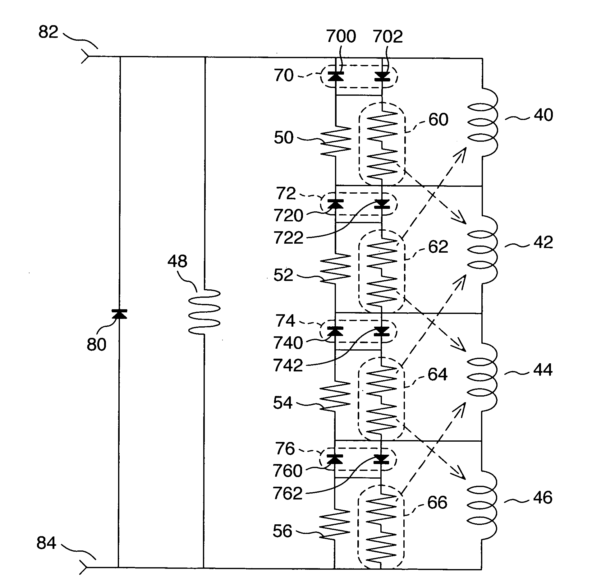
[0017]FIG. 1 shows a circuitry as one embodiment of this invention. This is a protection circuit for a multilayer coil made up of four coils and for a persistent current switch. Series-connected four superconducting coils 40, 42, 44, 46 and a persistent current switch 48 are connected in parallel, forming a main circuit. Shunt resistors 50, 52, 54, 56 are connected in parallel with the associated superconducting coils 40 to 46 to form divided protection circuits.

[0018] Resistive heaters 60, 62, 64, 66 are each made up of two unit heaters 600, 602, 620, 622, 640, 642, 660, 662 that are matched to the adjoining superconducting coils 40 to 46 as indicated by dashed arrows. That is, unit heater resistors 620, 622 connected in series with each other to form the heater resistor 62 heat different superconducting coils 40, 44 located nearby as indicated by dashed arrows. Other heater resistors 60, 64, 66 are also arranged in a similar manner to the heater resistor 62.

[0019] Diode pairs 70...

embodiment 2

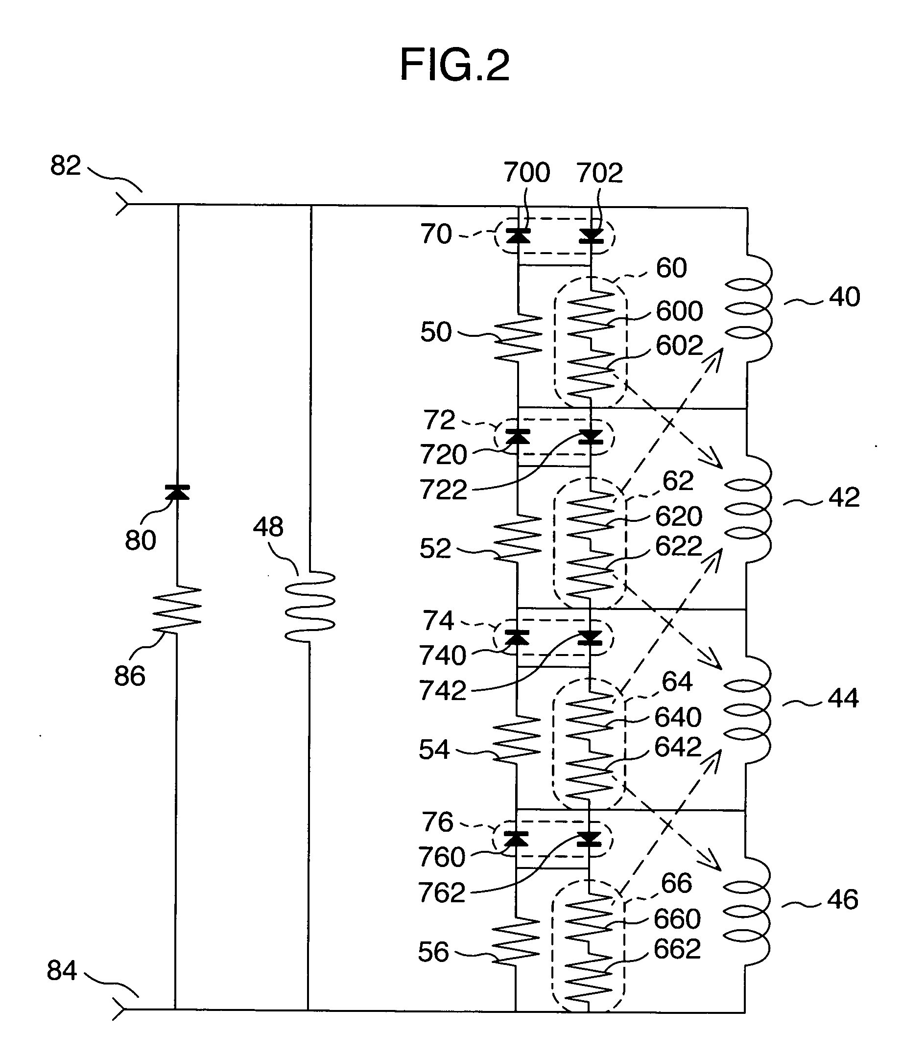
[0024]FIG. 2 shows a protection resistor 86 connected in series with the diode 80 applied to the protection circuit of the persistent current switch 2 in the circuit of FIG. 1. Like reference numbers denote the identical components of FIG. 1 and their explanations are omitted. While in FIG. 1 the energy stored in the persistent current circuit is recovered by the diode 80 in the event of the quench of the persistent current switch 48, this embodiment can recover the energy by the resistor 86 in addition to the diode 80. It is therefore possible to recover a greater amount of energy in a shorter period of time.

embodiment 3

[0025]FIG. 3 is a circuitry in which the diode 80 applied to the protection circuit of the persistent current switch 48 in FIG. 1 is replaced with a bidirectional diode 88 made up of unit diodes 880, 882. Like reference numerals denote the identical components of FIG. 1 and their explanations are omitted. The provision of the bidirectional diode 88 in this embodiment obviates the need to consider the polarity at time of excitation and deexcitation and thereby improves the ease of use. When the energy to be recovered is large or the time to recover the energy is reduced, protective resistors 90, 92 may be connected in series with the bidirectional diode 88 as in the embodiment 2 of FIG. 2.

[0026] Since this invention can realize easy-to-design protection circuits with high level of safety for superconducting coils and for a persistent current switch, it can be applied to NMR (nuclear magnetic resonance) and MRI (magnetic resonance imaging) equipment made up of a plurality of supercon...


PUM


Abstract

A superconducting magnet system includes resistive heaters and bidirectional diodes connected in series with each other installed in a superconducting coil protection circuit, and a diode is installed in a persistent current switch protection circuit.

Description

BACKGROUND OF THE INVENTION [0001] The present invention relates to a superconducting magnet system which has a superconducting coil and a persistent current switch and more particularly to a superconducting magnet system which has quench protection circuits for the superconducting coil and the persistent current switch. [0002] Superconducting coils capable of flowing a large current are often used in magnets required to generate strong magnetic fields, as in NMR (nuclear magnetic resonance) equipment. To use superconducting coils to generate strong magnetic fields that are stable at all times requires flowing an electric current in a persistent current mode. To establish the persistent current mode, a persistent current switch (PCS) is connected in parallel with the superconducting coils. [0003] The superconducting coils, however, have a problem of quench. In the event of a quench, if a protection circuit is not provided, energy stored in the superconducting coils is all consumed b...

Claims


Application Information

Patent Timeline
Patent Type & Authority Applications(United States)
IPC IPC(8): H02H7/00
CPCH02H7/001Y02E40/68Y02E40/60
Inventor TSUCHIYA, MITSUYOSHITAKEUCHI, KAZUHIROTSUKAMOTO, HIDEOWAKUDA, TSUYOSHI
Owner HITACHI LTD
Why Eureka
Try Eureka