Method and apparatus for joining linear lighting fixtures to eliminate sag

a technology of linear lighting fixtures and linear joints, which is applied in the direction of fixed installation, lighting and heating equipment, lighting support devices, etc., can solve the problems of reducing the aesthetic appeal of the lighting system, hazard to people and/or properties, etc., and achieves the effect of saving installation cost, safe hanging, and saving time during installation

Inactive Publication Date: 2006-07-20
GROUP DEKKO
View PDF14 Cites 12 Cited by
  • Summary
  • Abstract
  • Description
  • Claims
  • Application Information

AI Technical Summary

Benefits of technology

[0013] An advantage of the present invention is that two linear light fixtures can be safely hung using only two hangars.
[0014] Another advantage of the present invention is that two linear light fixtures can be hung using only two hangars without any misalignment or sag between the linear light fixtures.
[0015] Yet another advantage of the present invention is that it saves time during installation.
[0016] Yet another advantage of the present invention is that it saves cost during installation.
[0017] Yet another advantage of the present invention is that it is more cost effective to manufacture.
[0018] Yet another advantage of the present invention is that it is easier to install in that it does not require adjusting a third hangar to eliminate sagging of the fixtures.

Problems solved by technology

If one of the fixtures is misaligned or sags with respect to an adjoining fixture there is a less than attractive look to the lighting system, which diminishes the aesthetic appeal of the lighting system.
If the lighting system is not sufficiently structurally supported, and as the lighting fixtures can have relatively heavy metal housings which include the light source(s) and electrical components such as ballast systems, an insufficiently supported system can be a safety concern since such a system can potentially fall from the ceiling and a falling fixture is a hazard to people and / or property.

Method used


Image

  • Method and apparatus for joining linear lighting fixtures to eliminate sag
  • Method and apparatus for joining linear lighting fixtures to eliminate sag
  • Method and apparatus for joining linear lighting fixtures to eliminate sag

Examples


Embodiment Construction

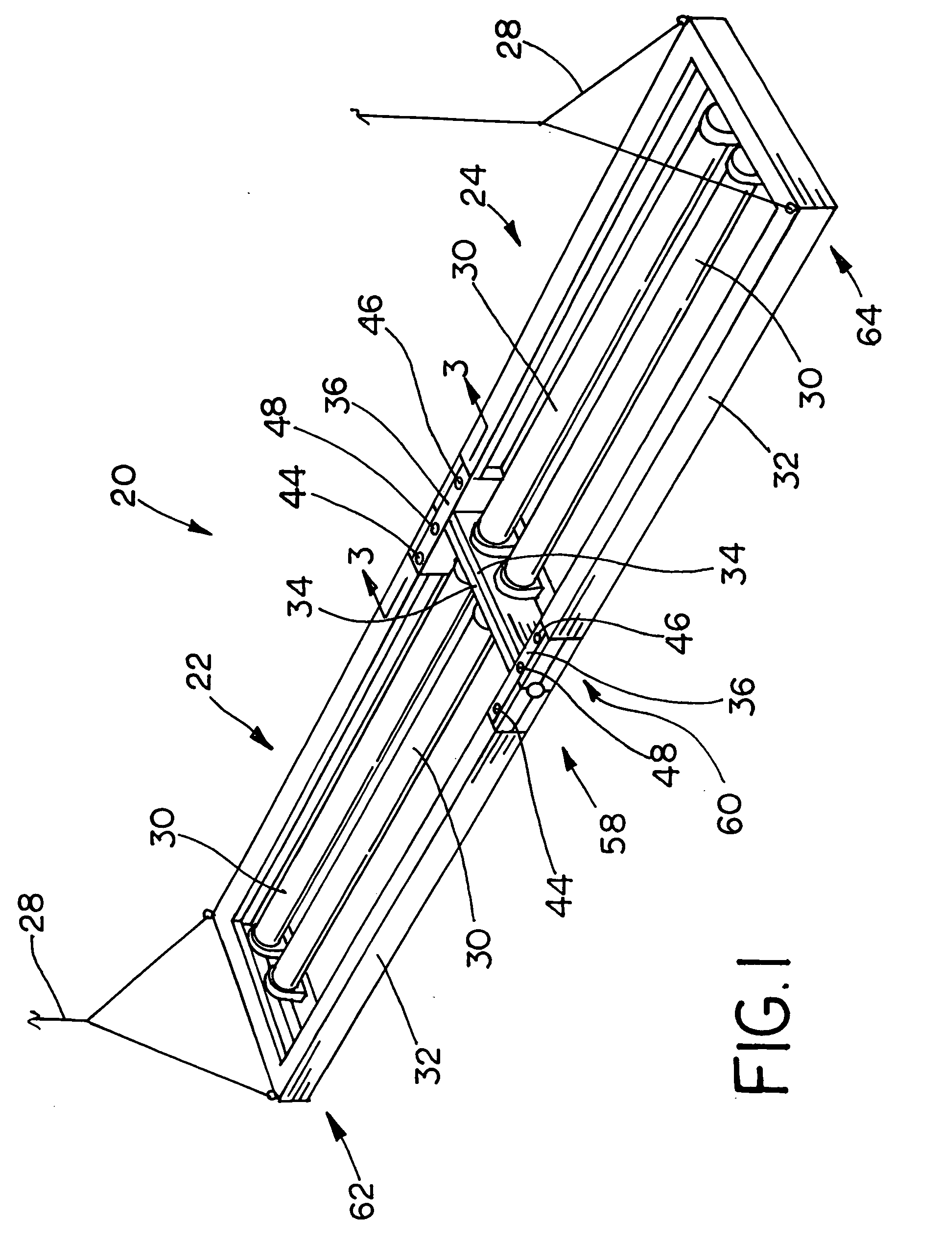
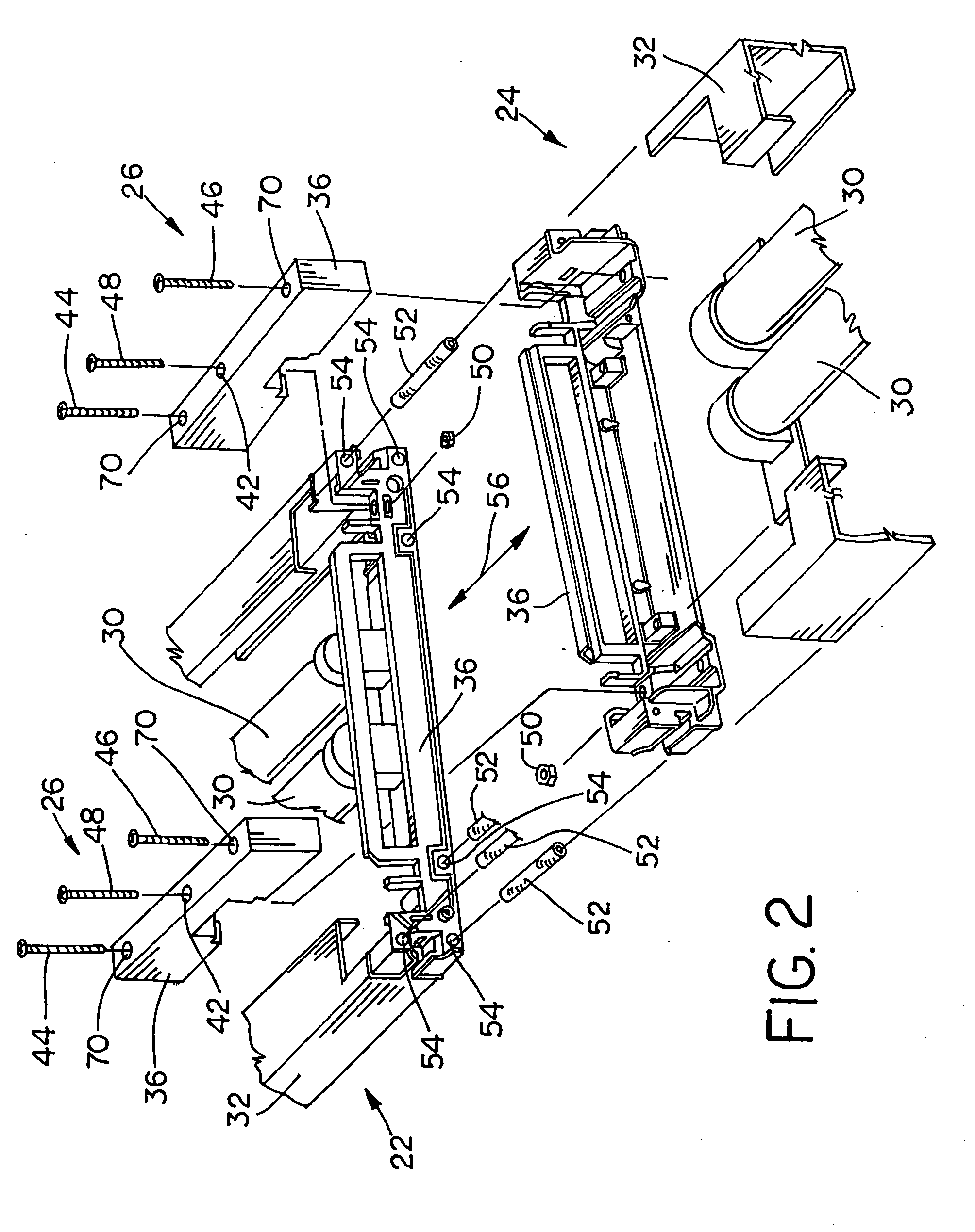
[0031] Referring now to the drawings, and more particularly to FIGS. 1 and 2, there is shown a linear lighting assembly 20, which generally includes a first linear light fixture 22, a second linear light fixture 24 connected to first linear light fixture 22, at least one joiner assembly 26 connected to first linear light fixture 22 and second linear light fixture 24, and hangars 28.

[0032] Each of fixtures 22, 24 include a source of light, such as fluorescent lamps 30, although other sources of light such as incandescent, light emitting diode arrays, metal halide, sodium, and the like, can be used. Each of fixtures 22, 24 includes a fixture housing 32 connected to lamps 30. Housings 32 include respective end brackets 34. Each of fixtures 22, 24 are connected to a source of electrical power (not shown) and can include other electrical components such as ballasts, controls, conductors, connectors, and the like (also not shown) electrically connected to lamps 30 and as are required to ...


PUM


Abstract

A joiner assembly for joining and supporting a first linear light fixture with a second linear light fixture. The joiner assembly includes a joiner bracket including first control surface connected to a second control surface and a draw fastener hole therebetween. The first control surface is configured for controlling a position of the first linear light fixture in a prestressed condition, and the second control surface is configured for controlling a position of the second linear light fixture in a prestressed condition. A draw fastener is connected to the draw fastener hole. A draw fastener constraint is connected to the draw fastener and configured for connection to at least one of the first linear light fixture and the second linear light fixture.

Description

CROSS REFERENCE TO RELATED APPLICATIONS [0001] This is a non-provisional application based upon U.S. provisional patent application Ser. No. 60 / 642,738, entitled “METHOD OF JOINING RECTILINEAR LIGHTING FIXTURES TO ELIMINATE SAG”, filed Jan. 10, 2005.BACKGROUND OF THE INVENTION [0002] 1. Field of the Invention [0003] The present invention relates to linear lighting fixtures, and, more particularly, to a method and apparatus for joining linear lighting fixtures to eliminate sag. [0004] 2. Description of the Related Art [0005] Linear light fixtures are known which are suspended from a ceiling using a wire cable hangar, or other type of hangars, at each end of the fixture. Such fixtures are sometimes suspended end for end in a linear array or combination of fixtures. It is advantageous to minimize the number of hangars used in such a system, in order to save installation cost and time. However, sufficient hangars, and / or other structural support, must be present in order maintain alignm...

Claims


Application Information

Patent Timeline
Patent Type & Authority Applications(United States)
IPC IPC(8): F21S4/00
CPCF21S8/06F21S8/061F21V21/005F21Y2103/00
Inventor LANCZY, GEZA T.
Owner GROUP DEKKO
Why Eureka
Try Eureka