Bone plate system and methods

a plate system and bone plate technology, applied in the field of bone plate systems, can solve the problems of compromising the ability to achieve optimal bone fusion, affecting the fusion process, so as to minimize undesirable plate movement, maximize coverage, and minimize the effect of bone plate movemen

Active Publication Date: 2006-07-20
XTANT MEDICAL HLDG INC
View PDF99 Cites 133 Cited by
  • Summary
  • Abstract
  • Description
  • Claims
  • Application Information

AI Technical Summary

Benefits of technology

[0015] In accordance with another aspect, a single retainer is provided for each bore. In this manner, adjustment of the longitudinal curve of the plate about a transverse axis extending orthogonal to the longitudinal axis of the plate can be made by adjusting the curve of the plate through plate portions spaced from the bores, preferably plate portions that extend longitudinally between the bores and which do not have the retainers or bores associated therewith. Accordingly, the location and position of the retainer relative to the plate and its bore are not affected by adjustment of the plate curvature, thus avoiding a potential problem in properly locating the screw in the bore below the retainer.
[0028] In another aspect, a tool for determining a plate size for a particular patient is provided. The tool is a sizing caliper having two legs which can be inserted together into a small incision and having a knob rotated to adjust the position of the legs relative to each other for determining a plate size. The sizing caliper may include a portion permitting the legs to be collapsed for withdrawal, and which then returns the legs to the measured position once withdrawn from the implant site so that the measurement is preserved. The sizing caliper may have a point or spike on one leg for securing in a selected position as the other leg is shifted relatively having a dull end or ball, or both legs may have ball shapes thereon for minimizing the risk of damage to surrounding tissues.

Problems solved by technology

If the screws loosen, the bones are not properly secure and may move relative to each other.
This may compromise the ability to achieve optimal bone fusion and bone alignment, or it may lead to loss of graft material, and damage or loss of bone.
Furthermore, when the plate is a dynamic or dynamized plate, such that at least some screws may move relative to the plate, these issues may be further compounded or exacerbated by a screw backing out.
However, heretofore known arrangements of fixed and dynamized apertures in such plates provide less than optimal capacity for controlling the movement and / or compression between more than two levels of secured vertebrae.
As the channel reduces the effective plate thickness, the curved plate is more prone to deforming under these compressive forces and moment arms.
The band itself must be secured with the plate by the retainers, which may result in a rough upper or top surface.
A rough surface, as well as significant plate thickness, can be uncomfortable or problematic for a patient during swallowing.
For an increased curve, the bands may be stretched which reduces their ability to shift as desired to permit screw securement and to return to their natural position and which may impair their general integrity.
Furthermore, an increase of the curvature of the plate draws the bands closer to and into the holes, reducing the ability to properly seat the screw underneath the band.
One problem with such a bone plate configuration is that forces on the plate and screws, such as moment arms from each level of screws to the lowest level, are greater.
Another problem is that, though the screws may translate in the slots, this translation is not precisely controlled or predictable, and the greater translation that is required results in a greater ability for graft material to explant due to this lack of control, or be crushed by bearing a greater than desired load.
This helps to reduce surgeon or surgical technician error in properly installing the retainers, as well as reduce the ability for someone to alter the shape of the retainers themselves.
Furthermore, the retainers require no additional steps to be properly positioned relative to the plate and, specifically, the screw openings or bores to limit screw back out.

Method used


Image

  • Bone plate system and methods
  • Bone plate system and methods
  • Bone plate system and methods

Examples


Embodiment Construction

)

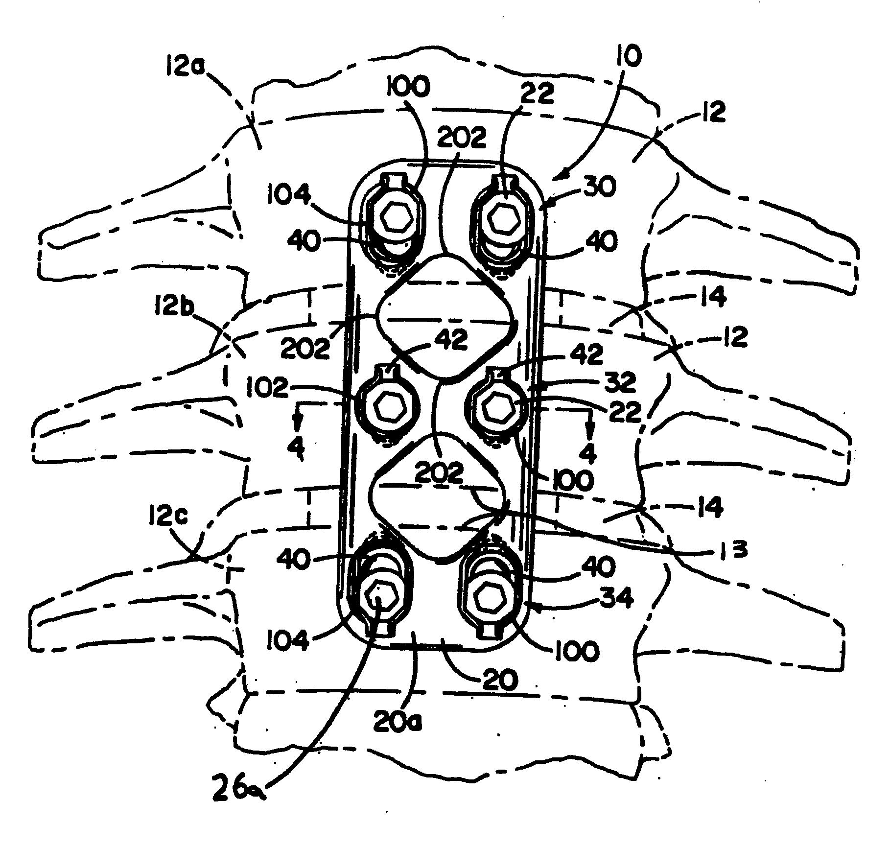
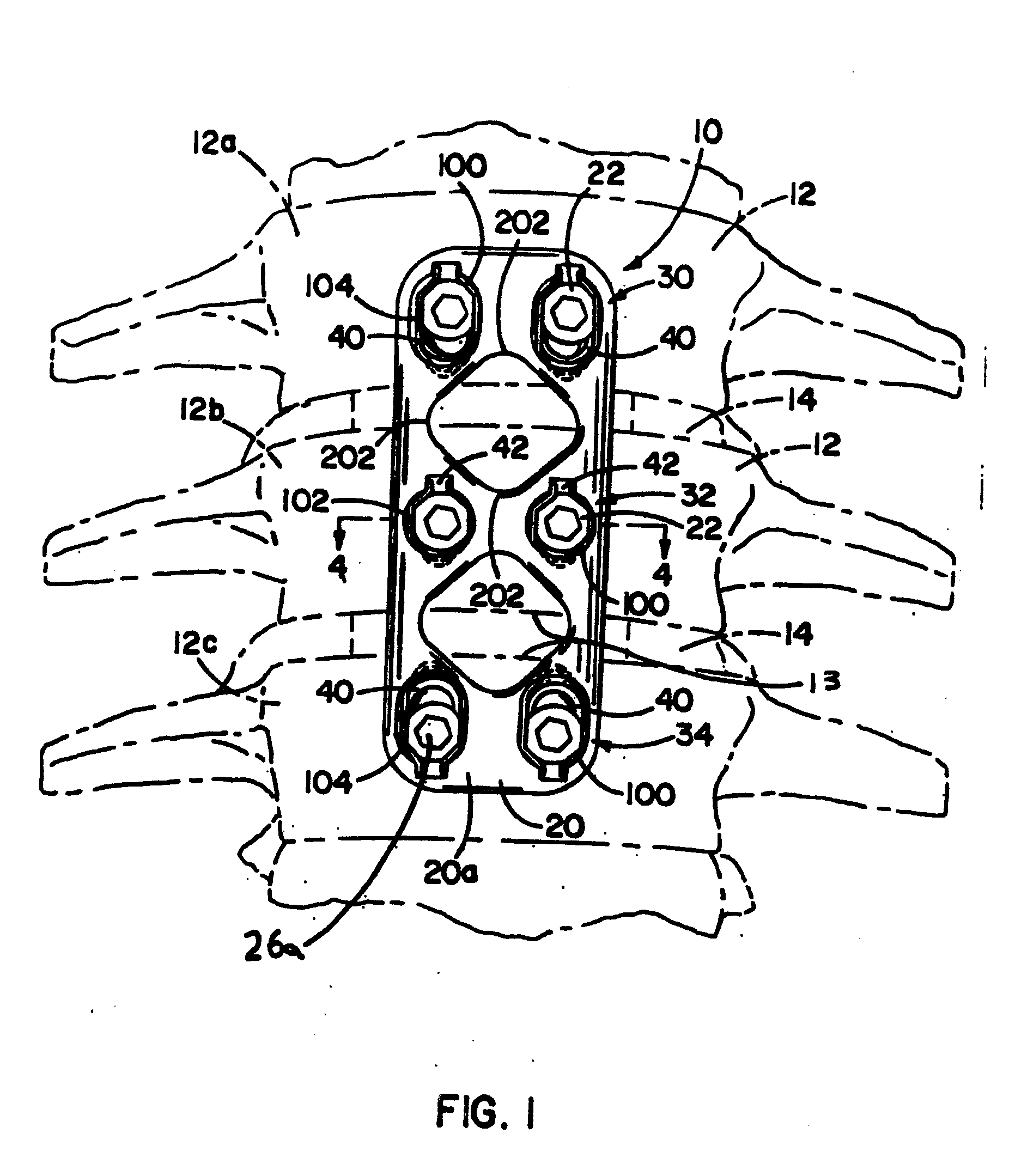
[0143] Referring to the FIGURES, exemplary bone plate systems for securing a plurality of bones 12 in a desired orientation or arrangement are illustrated including features in accordance with the present invention. In some forms, the bone plate system is a dynamized plate, or has at least one set of dynamic holes, so that bones 12 may compress and shift toward each other, such as the bone plate system 10 depicted in FIG. 1. In other forms, such as exemplified in FIG. 28, a bone plate system 700 is illustrated as non-dynamized. It should be noted that a bone plate system may be provided including a bone plate where each bore thereof is dynamic, as is described herein, or non-dynamic, also described herein. In addition, a dynamized bone plate may utilize a combination of dynamic and non-dynamic bores.

[0144] Referring now to FIG. 1, the bone plate system 10 assists in the healing and repair of damaged, fractured, or broken bones 12. In the illustration of FIG. 1, the bones 12 are ad...


PUM


Abstract

Bone plate systems and retainers are provided for surgical implants and bone repair. The bone plate is multi-tiered for receiving bone anchors or screws for securing multiple bones or bone fragments in a desired relationship. The plate includes bores for receiving the screws, and the bores may permit and define a translation path for the screws relative to the plate. The retainers are held in a recess in the bores to prevent screw back-out. Once the screw is seated with the plate, the retainer rests over a top surface of the screw to impede screw back-out from the plate. The retainer may expand to permit driving a screw therethrough and may contract once the screw is seated within the plate so the retainer is in a configuration for preventing back-out. Tools and methods are also provided for implantation and removal of the plates and the screws.

Description

CROSS-REFERENCE TO RELATED APPLICATIONS [0001] The present application is a continuation-in-part of U.S. patent application Ser. No. 10 / 973,891, filed Oct. 26, 2004, and titled “Bone Plate System and Methods,” which claims priority to U.S. Provisional Application Ser. No. 60 / 548,140, filed Feb. 26, 2004, and titled “Bone Plate with Spring Retainers,” the specifications of which are incorporated herein by reference.FIELD OF THE INVENTION [0002] The invention relates to bone plate systems and, more particularly, to a bone plate system including a retention system to retain the bone anchors against back from apertures of the plate, and to devices and methods for implanting and removing a bone plate system. BACKGROUND OF THE INVENTION [0003] There are presently many different types of plate and fixture systems for securing two or more bones or bone fragments in relative position so that the bones may fuse or heal, or so that tissue adjacent the bones may heal without disruption from the...

Claims


Application Information

Patent Timeline
Patent Type & Authority Applications(United States)
IPC IPC(8): A61F2/30A61B17/16A61B17/17A61B17/70A61B17/80A61B17/88A61B17/92A61B19/00
CPCA61B17/1615A61B17/1655A61B17/1671A61B17/1728A61B17/1757A61B17/7059A61B17/8009A61B17/8042A61B17/8863A61B17/8875A61B17/92A61B2019/304A61B2019/461A61B2090/034A61B2090/061
Inventor MOSCA, LAWRENCEGEPHART, MATTHEW PETERJANOWSKI, BRIANFREDIN, BRADKORHONEN, FRANCISSONGER, MATTHEW N.
Owner XTANT MEDICAL HLDG INC
Why Eureka
Try Eureka