System for wireless local display of measurement data from electronic measuring tools and gauges

a technology of electronic measuring tools and gauges, applied in the field of measuring tools, can solve the problems of many semi-automatic and manual processes, many hand tools are held in awkward positions, and measurements must be taken

Inactive Publication Date: 2006-07-27
FREIDIN PHILIP MANUEL
View PDF20 Cites 48 Cited by
  • Summary
  • Abstract
  • Description
  • Claims
  • Application Information

AI Technical Summary

Benefits of technology

[0028] In one embodiment referring now to the system described further above, the wireless protocol used is Bluetooth™ or Zigby™. In still another embodiment regarding the system, the measurement tool is a tool adapted to monitor resistance of a strain gauge and to record differences in resistance caused by deflection of a leaf spring supporting the strain gauge. In a variation of this embodiment, the leaf spring supports more than one strain gauge.

Problems solved by technology

Likewise, there are many semi-automated and manual processes that are used instead of fully automated processes for manufacturing parts.
Moreover, some products require multiple processes on different machines, with many measurement cycles interspersed in the overall processes before they can be finished.
One problem with using these conventional tools in fabrication is that often measurements must be taken several times for a particular dimension in order to check repeatability of the reading.
This is because these hand tools are often held in awkward positions when measuring dimensional features of stationary mounted parts.
A fabricator cannot be 100% sure in many cases that the tool did not move slightly when locking or even if the correct surface angle in relation to the part was achieved when taking the measurement.
There are other situations where the measurement tool could not be removed from the measurement position if it is locked.
These problems may be exasperating to the fabricator, especially if close dimensional tolerances are critical to the process.
In some cases, conventional gauge and dial-bearing tools are not sufficient to measure extremely tight tolerances, especially when awkwardly held to measure a part mounted in a vise, for example, on a milling machine.
Other processes that cause difficulty when using conventional measurement tools are those used to prepare a machine and machine components for accurate performance.
Due to the preferred angle of the indicator dial and tip positioned against the milling bed as it is rotated, when the display is 180 degrees opposite the fabricator, he or she cannot read the display easily, or at all.
Some dial indicators are available that have bidirectional tips, meaning that the display can be facing the fabricator when checking the near jaw, however, this may still prove inaccurate because the fabricator cannot see the near jaw surface the tip is traveling on.
However, these tools still have a unidirectional display, meaning that the display is viewable only when the fabricator is facing it.
In removing the tool, movement of measuring mechanisms may still occur, causing inaccurate readings.
Removing the tool may not be desirable if multiple or continuous measurements are to be made.
Such an implement would not be really practical for use in fabrication due to the inconvenience of the physical wire and stationary nature of the connected computer or printer station.
However, a tether must be used to connect the device to the measuring tool, which is an inconvenience in the work area.

Method used


Image

  • System for wireless local display of measurement data from electronic measuring tools and gauges
  • System for wireless local display of measurement data from electronic measuring tools and gauges
  • System for wireless local display of measurement data from electronic measuring tools and gauges

Examples


Embodiment Construction

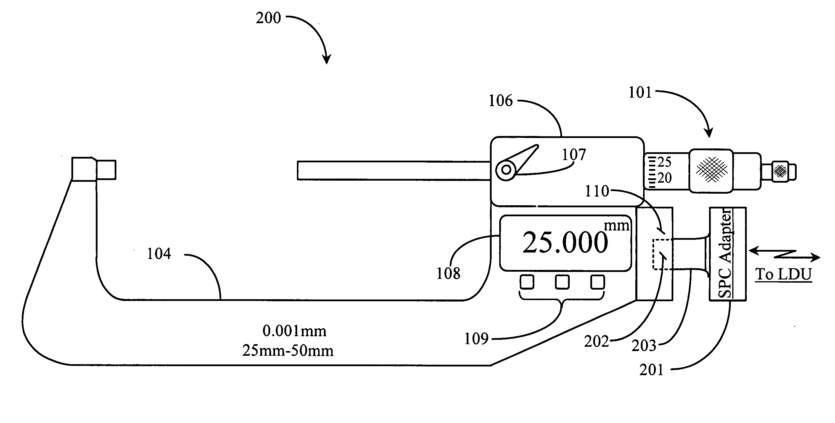
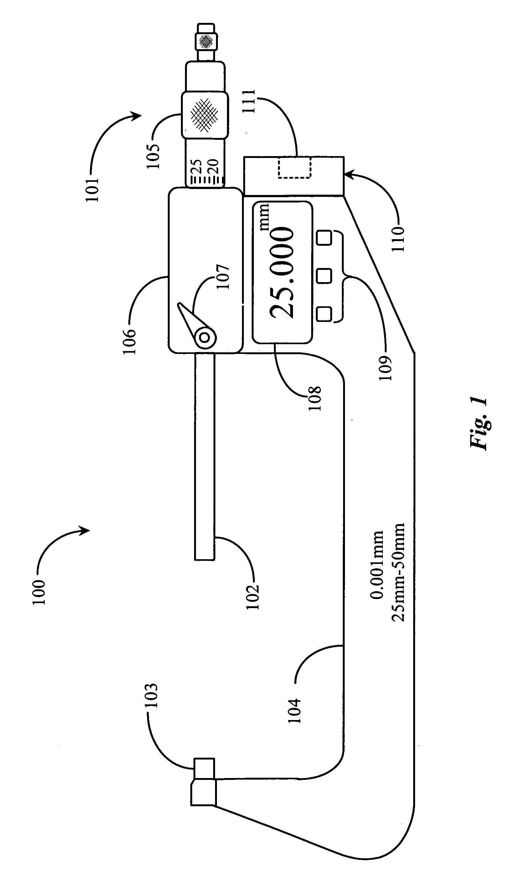
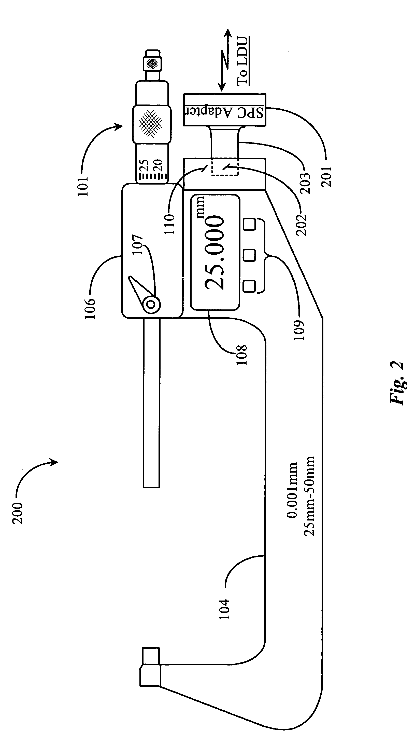
[0039]FIG. 1 is a plan view of a digital micrometer 100 and display according to prior art. Micrometer 100 is typical of a hand-held measurement tool used by persons in the art of machining of metals and other commonly machined or formed materials. Micrometer 100 has a rotatable and geared adjustment member 101 that is adapted to control the linear movement of a stainless steel shaft appendage 102. A micrometer tip 103 is adapted to abut against one surface of a material or work piece feature being measured, typically for thickness. Turning adjustment member 101 has a barrel feature 105 that has a scale engraved thereabout with a portion typically enlarged and crosshatched for user grip. Turning feature 105 clockwise moves member 102 toward the material or work piece until the end surface of member 102 makes contact with the opposite surface of the feature being measured. The measured distance between the stationary micrometer tip surface 103 and the end surface of member 102 is the...


PUM


Abstract

A system for acquiring and displaying data in a measurement process includes a local display unit enabled for wireless data reception, and a measuring tool for acquiring measurement data, the tool being enabled for wireless data transmission. The system is characterized in that the acquired data is transmitted from the measuring tool to the local display unit and displayed thereon.

Description

FIELD OF THE INVENTION [0001] The present invention is in the field of measuring tools used in product prototyping, fabrication and production, and pertains particularly to systems and methods for local wireless display of measured data from measuring tools and devices. BACKGROUND OF THE INVENTION [0002] In the art of fabrication of products there are a wide variety of machines and processes that are available and used in prototyping, fabricating, and manufacturing products of many materials, sizes, shapes, and dimensions. There are many different manufacturing arts of which selection for use in manufacturing depends on material specifications, dimensional requirements, and process requirements generally dictated by engineers, as those specific processes that will be needed to produce finished products. [0003] Common and well-known manufacturing arts include, but are not limited to, the arts of metal working, including forming, stamping, sheet metal working, and metal machining. Pla...

Claims


Application Information

Patent Timeline
Patent Type & Authority Applications(United States)
IPC IPC(8): G01B5/00
CPCG01B3/18H04Q9/00
Inventor FREIDIN, PHILIP MANUEL
Owner FREIDIN PHILIP MANUEL
Why Eureka
Try Eureka