Pivoting mount for a firearm accessory

a technology for firearm accessories and mounting brackets, which is applied in the direction of weapons, sighting devices, weapon components, etc., can solve the problems of time-consuming and difficult to attach or remove the scope from the base, and achieve the effect of reliable and repeated movement and rapid deploymen

Active Publication Date: 2006-07-27
SAMSON SCOTT W
View PDF20 Cites 62 Cited by
  • Summary
  • Abstract
  • Description
  • Claims
  • Application Information

AI Technical Summary

Benefits of technology

[0009] In this regard, the present invention provides a modular accessory mount that interfaces with the desired accessory and allows the accessory to be reliably and repeatedly moved between an active position and an inactive position. In accordance with the present invention, a new and novel pivoting accessory mount is provided for use with a variety of sighting scopes such as are used on prior art firearms including, civilian and military rifles, shotguns, black-powder weapons and handguns. The pivoting mount of the present invention is useful for mounting one or both of a primary optical sight and for a secondary sighting accessory. For example, an optical scope may be mounted using the pivoting mount thereby allowing the scope to be pivoted to the side should the user wish to use the open sights on the firearm while also allowing the scope to be quickly positioned into the active position when needed. Similarly, an accessory sighting device can be mounted fir coordinated use with a primary sighting device using the pivot mount of the present invention, wherein the accessory can be pivoted out of the way when not needed but can also be quickly deployed when desired by the user.
[0010] The pivoting accessory mount of the present invention is designed to allow quick and easy engagement and disengagement of accessory devices, such as sighting devices, on prior art firearms without the need to re-adjust or re-zero the accessory each time it is deployed. The present invention also includes features that allow it to be tailored particularly for use in the modern type sporting rifle that includes some form of receiver rail mounting system in that the present invention can include modular interface components that make it particularly flexible and customizable for a variety of applications.
[0012] Accordingly, it is an object of the present invention to provide a pivoting mount for a firearm accessory. It is a further object of the present invention to provide a pivoting mount for a firearm accessory that has an engaged position that ensures positive alignment and repeatable results after multiple operations. It is still a further object of the present invention to provide a pivoting mount for a firearm accessory that is highly durable and easily operable to allow a user quick and positive operation between an engaged and disengaged position.

Problems solved by technology

In this regard, there are a number of different types and configurations of sight mounting devices that allow the sight to be removed from and replaced on to the firearm, each of which includes its own design problems and disadvantages.
Thus, it is often difficult and time consuming to attach or remove the scope from the base.

Method used


Image

  • Pivoting mount for a firearm accessory
  • Pivoting mount for a firearm accessory
  • Pivoting mount for a firearm accessory

Examples


Embodiment Construction

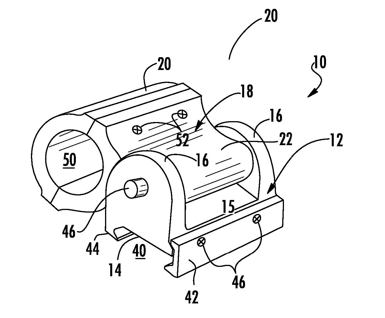
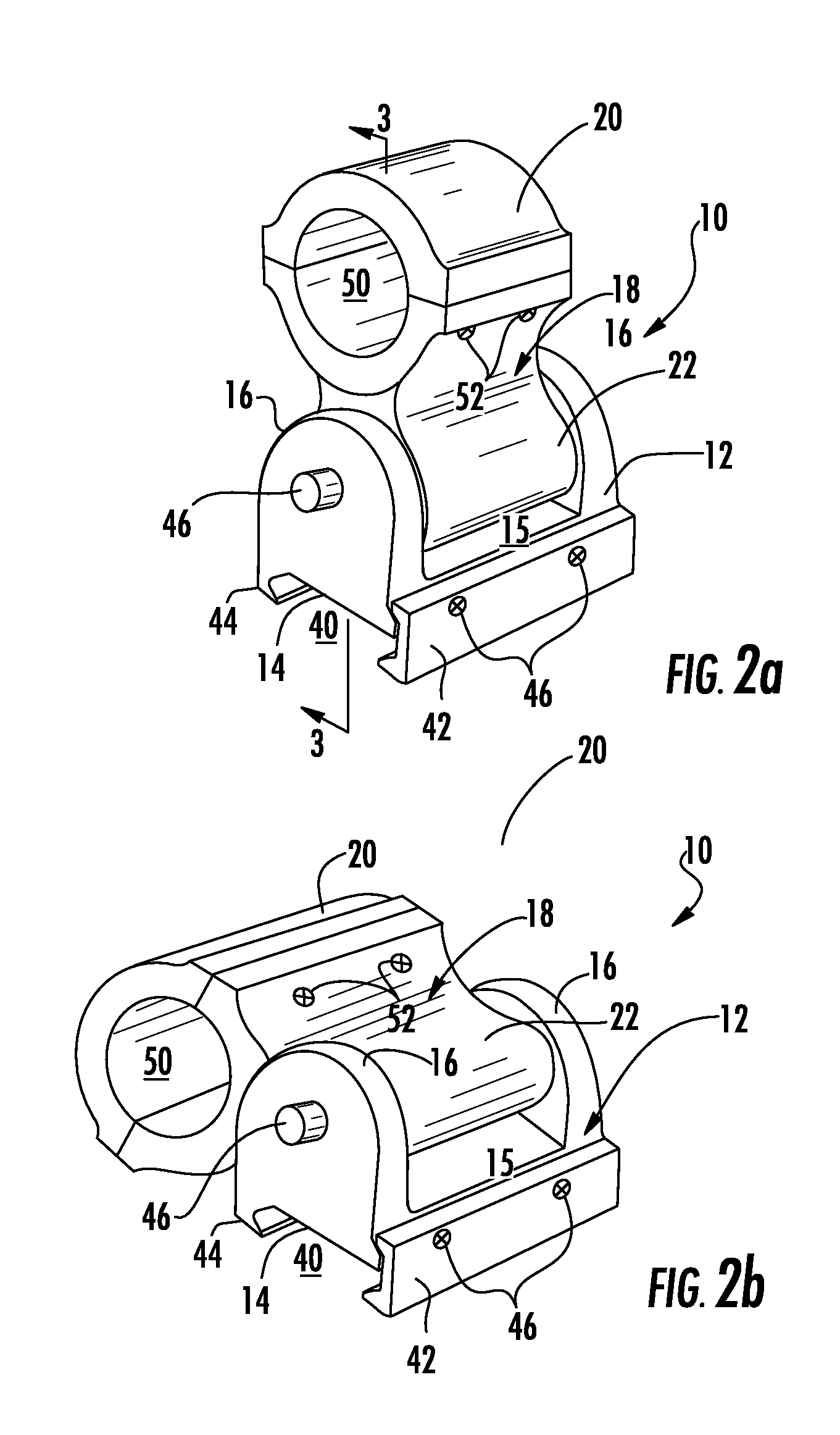
[0023] Now referring to the drawings, the pivoting accessory mount system of the present invention is shown and generally illustrated in the figures. As can be seen in FIG. 2a the pivoting accessory mount 10 generally includes a base member 12 having a bottom surface 14 configured to engage a firearm and a top surface 15 that includes at least one support element 16 extending upwardly therefrom. In addition, the accessory mount 10 includes an accessory receiver 18 with an upper portion 20 that forms an accessory clamp and a bottom portion 22 for interfacing with a mounting shaft 24 and attaching the accessory receiver 18 to the base member 12 as will be described in detail below.

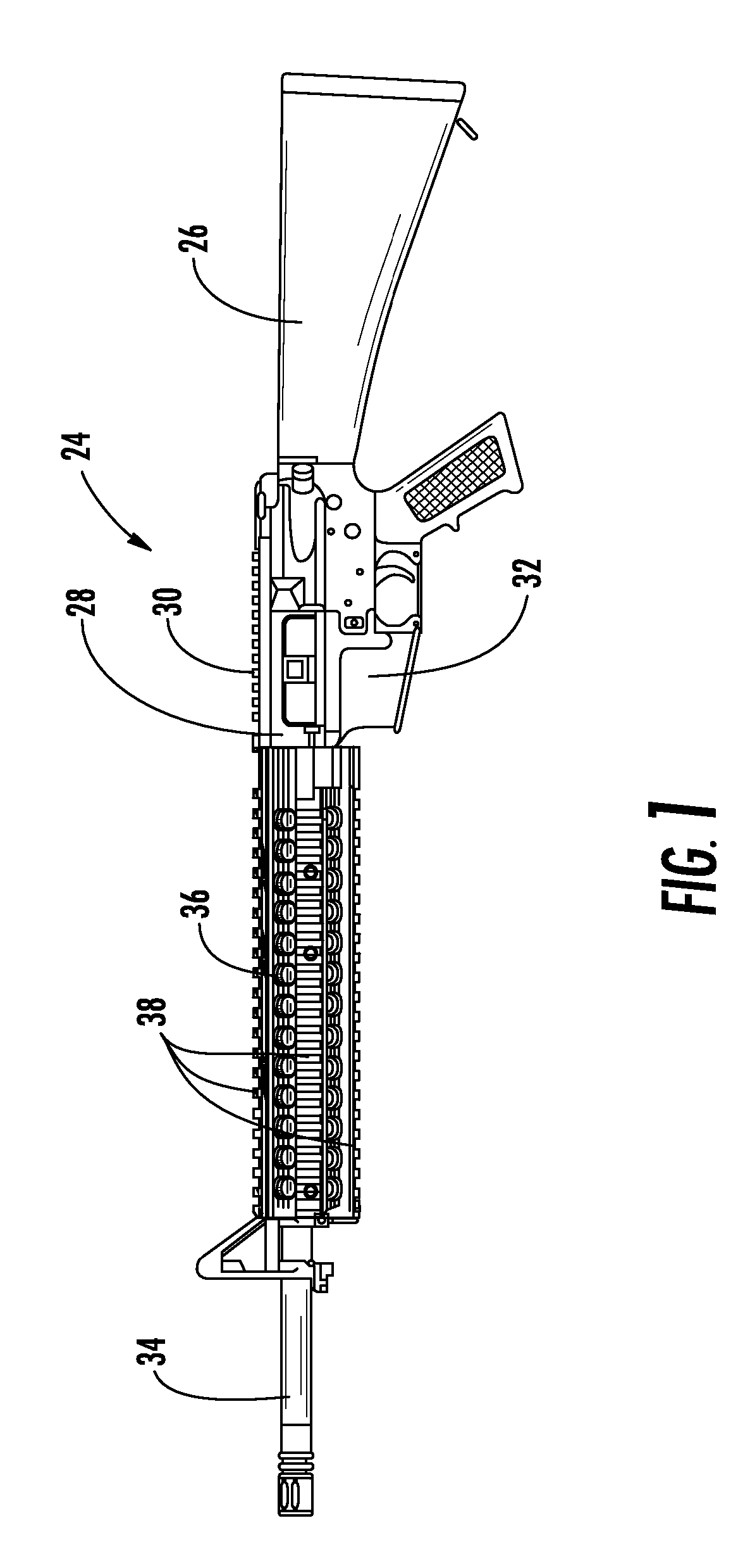
[0024] The accessory mount 10 of the present invention is intended for use with any known type of firearm including handguns, black powder weapons, sporting rifles and military rifles. For the purpose of illustration a typical military combat firearm 24 is depicted in FIG. 1. A conventional combat firearm 2...


PUM


Abstract

A pivoting accessory mount used for attaching auxiliary devices such as sighting devices to a firearm. The accessory mount includes a base member that attaches to the firearm and includes a mounting support and a shaft. An accessory receiver is pivotally received and retained about the shaft. The accessory receiver is pivotable between an inactive position along the side of the upper receiver of the firearm and an active position extending substantially vertically relative to and in alignment with the upper receiver of the firearm. The mounting shaft is linearly displaceable, thereby engaging the accessory receiver when in the active position to prevent accidental displacement of the accessory receiver.

Description

CROSS-REFERENCE TO RELATED APPLICATIONS [0001] This application is related to and claims priority from earlier filed U.S. Provisional Patent Application No. 60 / 647,622, filed Jan. 27, 2005, the contents of which are incorporated herein by reference.BACKGROUND OF THE INVENTION [0002] The present invention relates generally to a pivoting mounting assembly for interfacing accessories with firearms. More specifically, the present invention is related to a pivoting mount for a firearm accessory that allows the user to mount an accessory in a manner wherein the user can selectively pivot the accessory between an active position and an inactive position thereby providing for rapid changes between desired accessories. [0003] In the prior art there is a broad range of accessories that are mounted onto a firearm to provide increased accuracy or broader functionality. Similarly, many accessories are available that are configured to be paired with another accessory wherein the combination provi...

Claims


Application Information

Patent Timeline
Patent Type & Authority Applications(United States)
IPC IPC(8): F41G1/00
CPCF41C27/00F41G1/00F41G11/003F41G11/008
Inventor SAMSON, SCOTT W.
Owner SAMSON SCOTT W
Why Eureka
Try Eureka