Torque transducer assembly

a technology of torque transducer and assembly, which is applied in the direction of force sensors, rotating screw stopper insertion, cap, etc., can solve the problems of high cost, time-consuming, difficult to measure the amount of capping torque applied by a capping system, etc., and achieves a relatively inexpensive solution, simple, quick and effective

Inactive Publication Date: 2006-07-27
STRESS ENG SERVICES
View PDF16 Cites 14 Cited by
  • Summary
  • Abstract
  • Description
  • Claims
  • Application Information

AI Technical Summary

Benefits of technology

[0010] One advantage of the present invention is its provision of a simple, quick, effective, and relatively inexpensive solution for measuring the capping torque applied by a capping system. Additional aspects, advantages, and novel features of the invention will be set forth in part in the description that follows an

Problems solved by technology

As containers are typically designed for efficiency to include as little material as possible, threaded neck portions often can only withstand capping torques that slightly exceed the capping torque required to seal the container.
Conversely, inherent variation in capping machinery may result in a capping application to

Method used


Image

  • Torque transducer assembly
  • Torque transducer assembly
  • Torque transducer assembly

Examples


Embodiment Construction

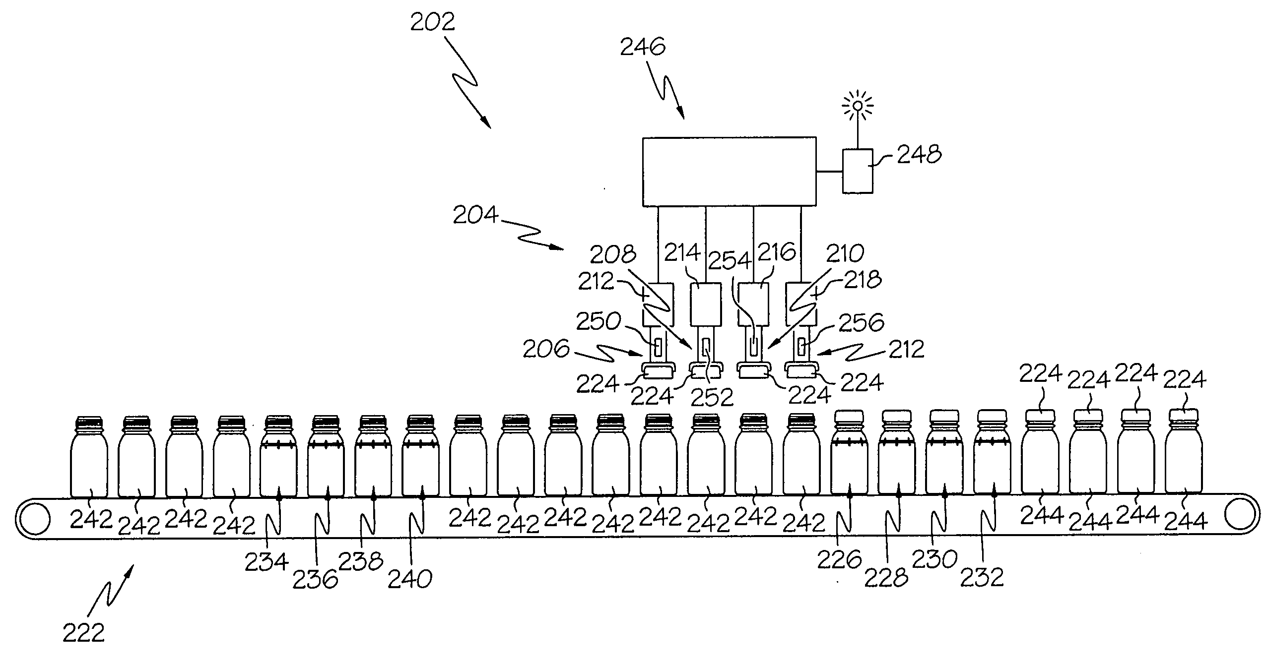
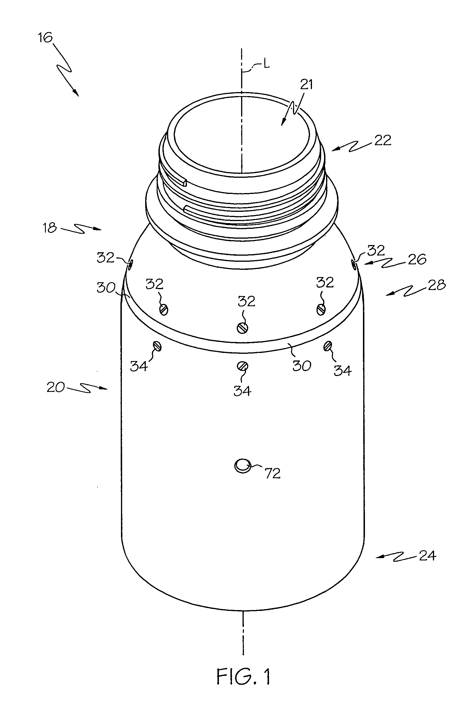
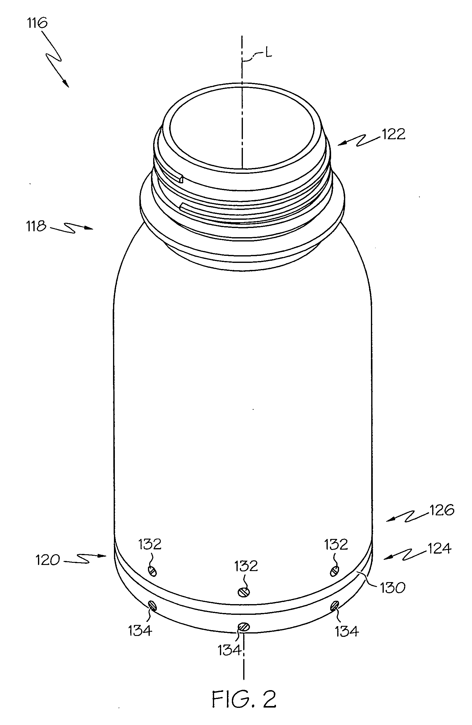
[0028] The present invention and its operation is hereinafter described in detail in connection with the views and examples of FIGS. 1-16, wherein like numbers indicate the same or corresponding elements throughout the views. These embodiments are shown and described only for purposes of illustrating examples of elements of the invention, and should not be considered as limiting on alternative structures or assemblies that will be apparent to those of ordinary skill in the art. Referring to FIG. 1, a torque transducer assembly 16 is depicted. The torque transducer assembly 16 can have an external configuration that is sufficiently similar to that of an ordinary container such that the torque transducer assembly 16 can be capped along with normal containers (e.g., as shown and discussed later with respect to FIG. 9) without substantially interfering with the capping process (i.e., the torque transducer assembly can have a size and shape that won't jamb the conveyor and / or capping sys...


PUM


Abstract

A torque transducer assembly includes a first shell having a threaded neck and a distal end. A second shell is also provided. A sensor module includes a first frame member, a second frame member, and a sensor. The first frame member is attached to the first shell and the second frame member is attached to the second shell such that the first and second shells are coupled to one another. A method of manufacturing a torque transducer assembly is also provided. A packaging system including a torque transducer assembly is additionally provided.

Description

TECHNICAL FIELD [0001] The present invention relates to a torque transducer assembly that can be introduced to a capping system for measuring the amount of torque applied during a capping process. The torque transducer assembly can include electronics for storing and / or transmitting the measured torque and / or other measured parameters. BACKGROUND OF THE INVENTION [0002] Containers (e.g., bottles) with screw-type caps or lids are commonly used for packaging of nearly an endless variety of consumer goods. After such containers are filled with their desired contents, they are typically presented to a capping system which presents and rotates a threaded cap onto a threaded neck of the container until the cap is sufficiently tightened for sealing the container. The amount of capping torque required to fully seal the cap upon a container varies depending upon many factors including, for example, the size and thread configuration of the container's threaded neck. As containers are typicall...

Claims


Application Information

Patent Timeline
IPC IPC(8): B65B7/28
CPCB65B7/2835B67B3/261G01L5/0042
Inventor HAYNES, CLINTON A.MARRIOTT, DOUGLAS L.BUCHHOLZ, TODD J.MILLER, WILLIAM A. JR.JOHNSON, RANDE T.ROBBINS, ERIC M.
Owner STRESS ENG SERVICES
Why Eureka
Try Eureka