

Apparatus and method for controlling roller rotation of laminator
- Summary
- Abstract
- Description
- Claims
- Application Information
AI Technical Summary
Benefits of technology
Problems solved by technology
Method used
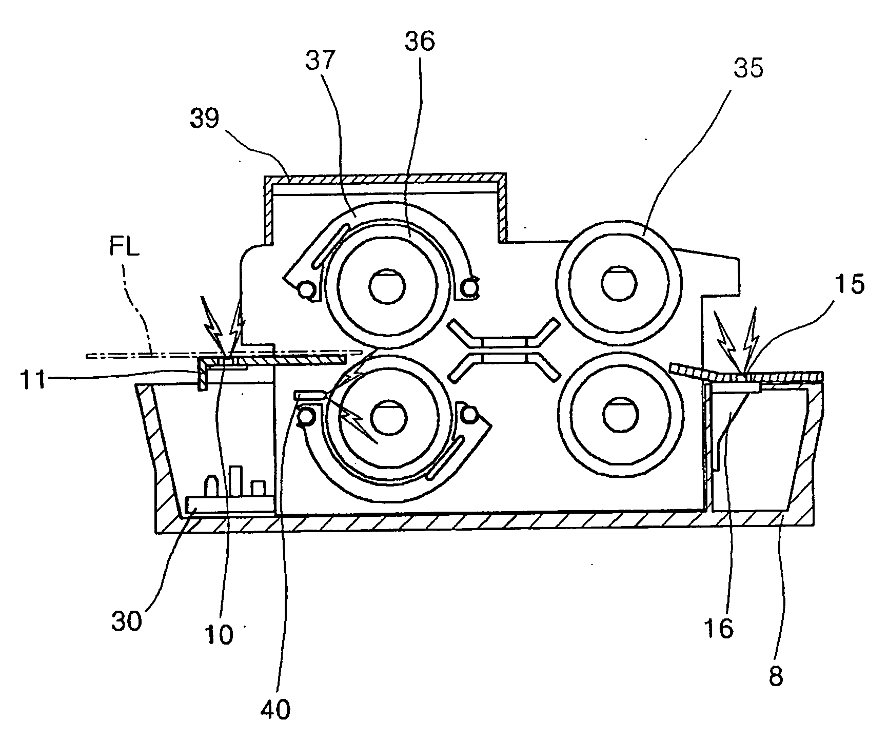
Image

Examples
Embodiment Construction
[0023] A preferred embodiment of the present invention will now be described with reference to the accompanying drawings. The matters defined in the description such as a detailed construction and elements are nothing but the ones provided to assist in a comprehensive understanding of the invention. Thus, it is apparent that the present invention can be carried out without those defined matters. Also, well-known functions or constructions are not described in detail since they would obscure the invention in unnecessary detail.
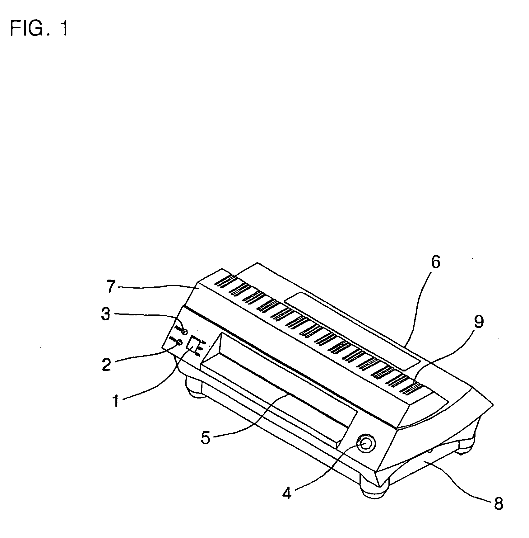
[0024]FIG. 1 is a perspective view of an appearance of a laminator adopting an apparatus for controlling roller rotation of a laminator according to the present invention.
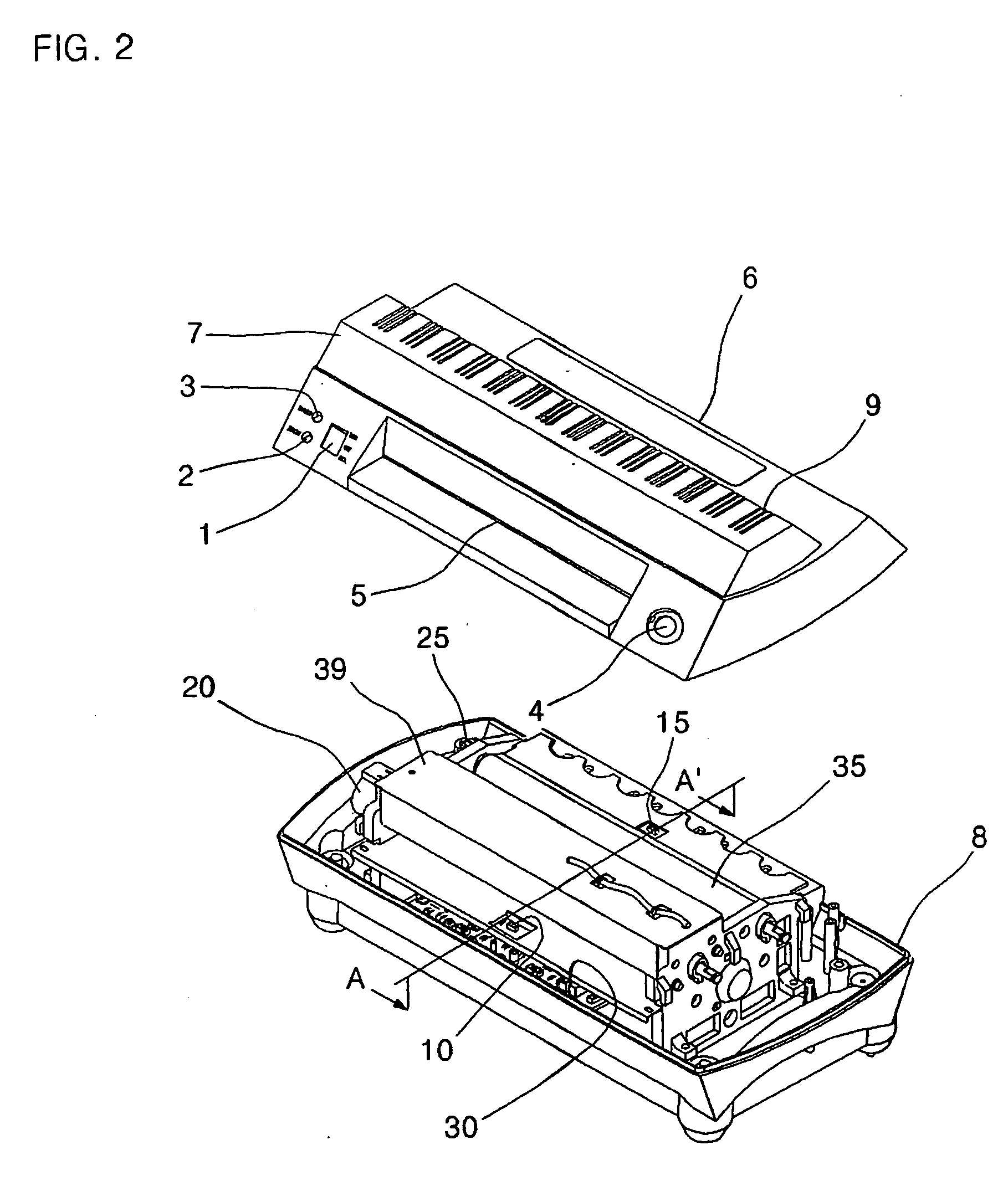
[0025] Referring to FIG. 1, an appearance of the present invention includes an upper cover 7 and a lower cover 8 forming an appearance of the laminator, and the upper cover 7 includes: a power switch 1 for controlling on / off of the laminator, a standby indicating lamp 2 for indicating an ope...
PUM
| Property | Measurement | Unit |
|---|---|---|
| Time | aaaaa | aaaaa |
| Time | aaaaa | aaaaa |
| Temperature | aaaaa | aaaaa |
Abstract
Description
Claims
Application Information