Tape cartridge

a tape cartridge and tape technology, applied in the field of tape cartridges, can solve the problems of inability to prevent the transfer of shapes, dropout, and durability in long-term use, and achieve the effect of reducing the step size, reliable rewinding of magnetic tapes 4, and simplifying the winding operation of magnetic tapes

Inactive Publication Date: 2006-07-27
HITACHT MAXELL LTD
View PDF0 Cites 3 Cited by
  • Summary
  • Abstract
  • Description
  • Claims
  • Application Information

AI Technical Summary

Benefits of technology

[0009] The non-recording layer M1 may be composed of an amount of the magnetic tape 4 which allows a wound posture to be maintained by a friction resistance between adjacent tape faces.
[0010] In the present invention, the one end of the magnetic tape 4 and the tape take-up-side hub 3 are connected via the leader tape 14 while the other end of the magnetic tape 4 is connected to the tape supply-side hub 2 in the state of being directly wound onto the tape supply-side hub 2. In this state, the wound tape layer wound onto the tape supply-side hub 2 is constituted of a non-recording layer M1 on the winding leader side composed of a specified winding amount of magnetic tape 4 and a recording layer M2 continuing to the non-recording layer M1, and the feeding limit position of the magnetic tape 4 in the tape supply-side hub 2 is set to be in the vicinity of a boundary between the non-recording layer M1 and the recording layer M2. Thus, while the end portion of the magnetic tape 4 directly wound onto the tape supply-side hub 2 causes a step by a thickness of the magnetic tape 4 at the winding leader, a step size can be drastically decreased compared to the case where, for example, a tape clamp 13 is used to secure the magnetic tape 4. Moreover, the step is absorbed by the non-recoding layer M1 wound onto the tape supply-side hub 2, and on the outermost perimeter of the non-recoding layer M1, the step is reshaped to a negligible level. Therefore, by providing the non-recoding layer M1 including an amount of the wound tape layer which allows the step to be reshaped, it becomes possible to suppress the transfer of shapes associated with the step corresponding to the thickness of the winding leader of the magnetic tape 4 and to sweep away the dropout of recording signals associated with the transfer of shapes so as to obtain a high-speed and high-density tape cartridge suitable as a backup medium for computer data.
[0011] The backup data is recorded only onto the recording layer M2 and at the point of time when all the recording layer M2 was fed, supplying of the tape is stopped so that the non-recoding layer M1 is constantly left on the supply-side hub 2. As a result, while the magnetic tape 4 is simply wound onto the supply-side hub 2, it becomes possible to reliably prevent the magnetic tape 4 from being separated from the supply-side hub 2 in the state that all the recording layer M2 was fed, thereby allowing reliable rewinding of the magnetic tape 4.
[0012] By bonding the end portion of the magnetic tape 4 to the peripheral face of the tape supply-side hub 2 through either water or the adhesive agents 17 and winding the end portion of the magnetic tape 4 in this state, the winding operation of the magnetic tape 4 can be simplified as well as the tape connection structure can be simplified by omission of the tape clamp or its mounting recess portion. Since the peripheral face shape of the hub 2 onto which the magnetic tape 4 is wound may be formed into a seamless circle, it becomes possible to methodically wind the magnetic tape 4 onto the hub 2 to surely prevent dropout of information signals in the recording layer M2.
[0013] By constituting the non-recoding layer M1 from an amount of the magnetic tape 4 which allows the wound posture to be maintained by a friction resistance between adjacent tape faces, it becomes possible to prevent the non-recoding layer M1 from going slack and being separated from the hub 2 even in the case where the tape cartridge is injected from a tape drive due to failures of the tape drive and the like in the state that all the amount of the recording layer M2 was fed.

Problems solved by technology

The shapes of these steps are transferred to the magnetic tape and thereby deforms the magnetic tape, which contributes to occurrence of dropout at the time of read / write access to recording signals.
However, it is necessary to connect the leader tape and the magnetic tape through the splicing tape, which makes it impossible to prevent the transfer of shapes caused by a step by a thickness of the splicing tape.
However, a large tape tension acts on the magnetic tape in the state that the magnetic tape is all fed, which causes a problem with durability in long-term use.
In addition, the tape end is bonded and fixed to the leader portion of the magnetic tape, and therefore it is unavoidable for the winding leader to have a step by the thickness of the tape.
Consequently, how to eliminate the dropout associated with the transfer of shapes is an issue to be solved.

Method used


Image

  • Tape cartridge
  • Tape cartridge
  • Tape cartridge

Examples


Embodiment Construction

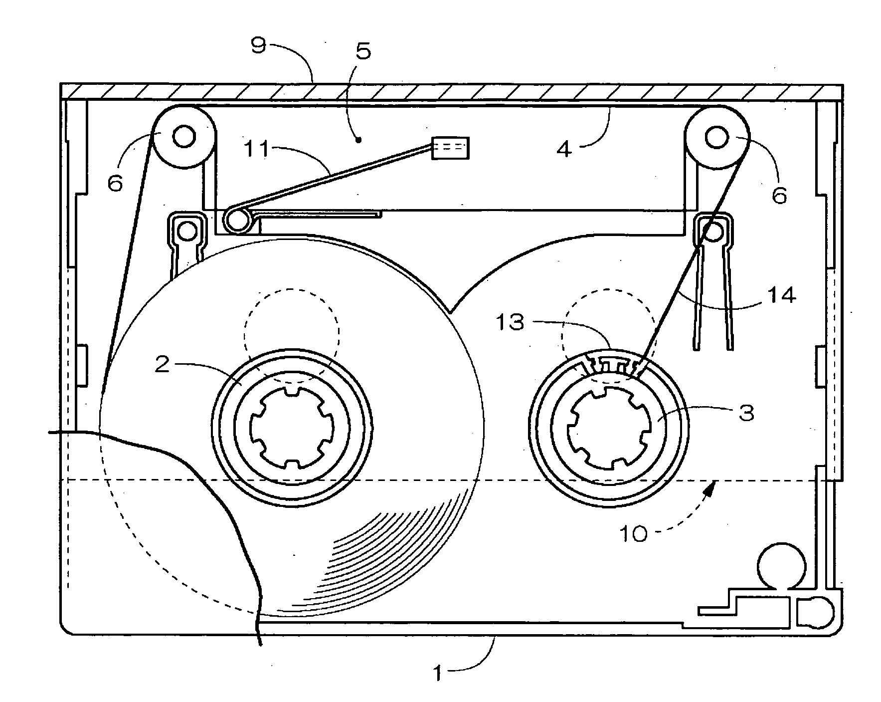
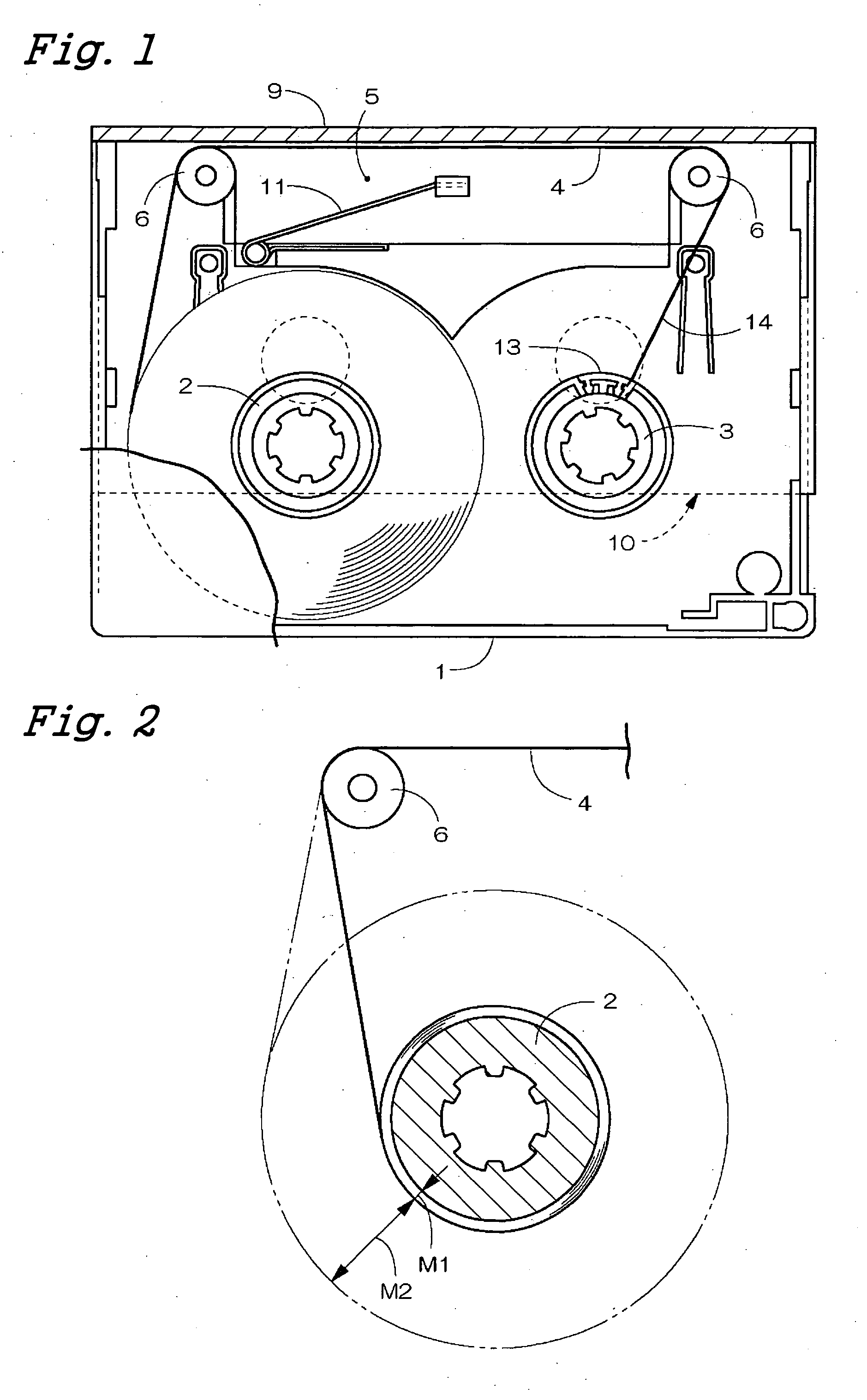
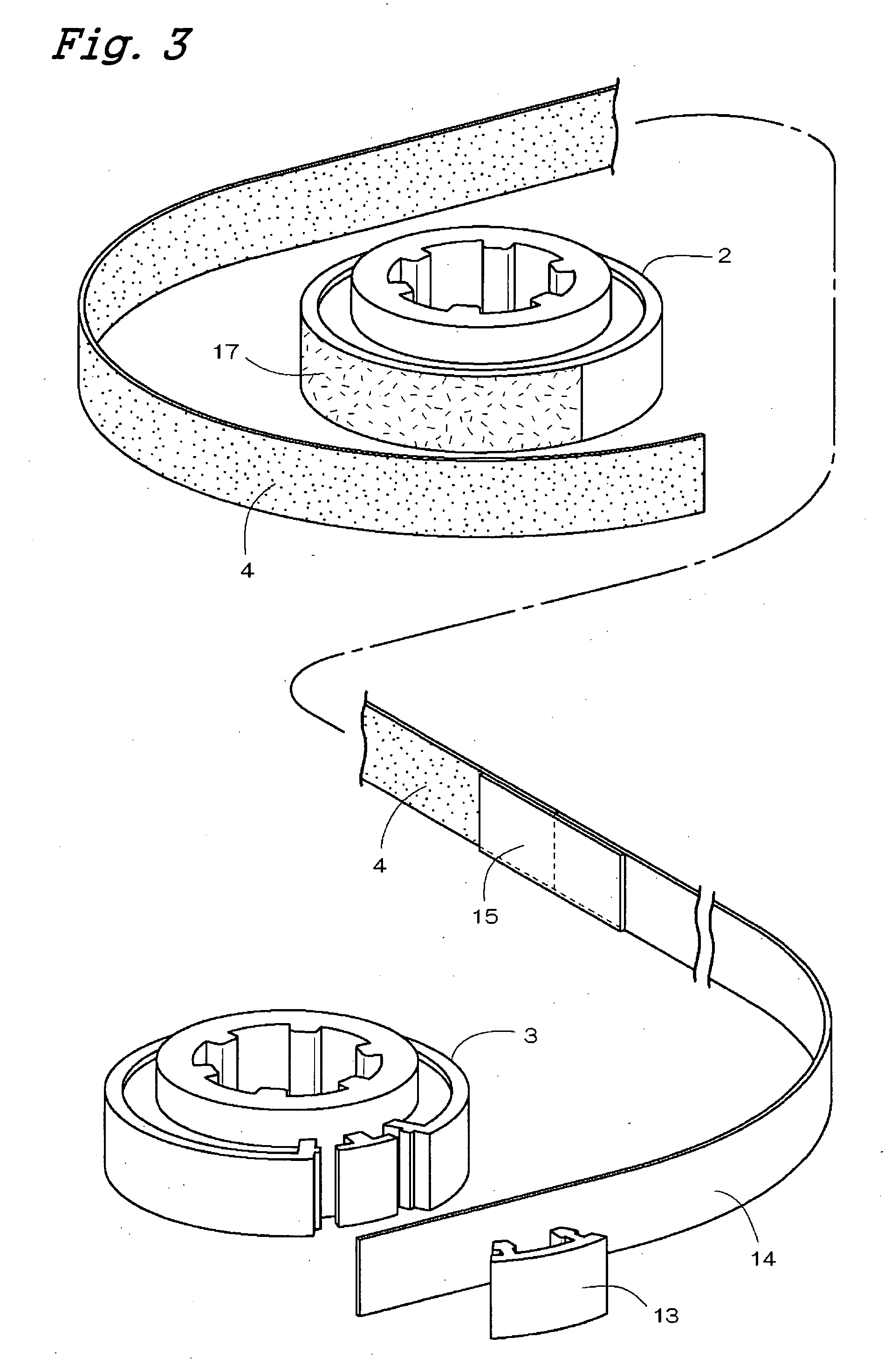
[0018]FIGS. 1-3 show the embodiment of a tape cartridge according to the present invention. In FIG. 1, the tape cartridge is composed of a tape supply-side hub 2 and a tape take-up-side hub 3 disposed on the left-hand and right-hand portions inside a mainframe case 1, and is capable of recording information signals by feeding the magnetic tape 4 wound onto the tape supply-side hub 2 to the tape take-up-side hub 3. A tape loading pocket 5 is provided on the front portion of the mainframe case 1. The magnetic tape 4 fed from the tape supply-side hub 2 is fed to the tape take-up-side hub 3 via tape guides 6, 6 disposed on both the sides of the pocket 5.

[0019] The tape loading pocket 5 can be opened and closed by rocking a front cover 9 and can also be opened and closed by sliding a shutter 10 disposed on the lower face side of the mainframe case 1. Reference numeral 11 denotes a spring for closing the shutter 10 by automatically applying a biased sliding force. The front cover 9 and t...


PUM

PropertyMeasurementUnit
magneticaaaaaaaaaa
friction resistanceaaaaaaaaaa
thicknessaaaaaaaaaa

Abstract

A tape supply-side hub, a tape take-up-side hub and a magnetic tape wound onto the tape supply-side hub are included inside a mainframe case. A leader tape fixed onto the tape take-up-side hub and one end of the magnetic tape are connected via a splicing tape. The other end of the magnetic tape is wound onto the tape supply-side hub, and the magnetic tape and the tape supply-side hub are directly connected with adhesive agents. A wound tape layer wounded onto the tape supply-side hub in the fully wound state is composed of a non-recording layer on the winding leader side composed of a specified amount of the wound tape layer and a recording layer continuing to the non-recording layer. The feeding limit position of the magnetic tape in the tape supply-side hub is set to be in the vicinity of a boundary between the non-recording layer and the recording layer.

Description

BACKGROUND OT THE INVENTION [0001] The present invention relates to a tape cartridge for use as a backup medium for computer data, and more particularly relates to a two-reel-type tape cartridge (DDS series) including a tape supply-side hub and a tape take-up-side hub placed inside a mainframe case. [0002] In the two-reel-type tape cartridge, respective end portions of the magnetic tapes are connected to hubs through leader tapes. In most cases, the magnetic tape and the leader tape are connected via a splicing tape, and the winding leader of the leader tape is fixed by a tape clamp mounted on the peripheral face of the hub. In such conventional tape connection structure, it is inevitable to have slight steps in a mounting portion of the tape clamp and in a bonding portion of the splicing tape. The shapes of these steps are transferred to the magnetic tape and thereby deforms the magnetic tape, which contributes to occurrence of dropout at the time of read / write access to recording ...

Claims


Application Information

Patent Timeline
Patent Type & Authority Applications(United States)
IPC IPC(8): G11B23/087
CPCG11B23/087G11B23/08728
Inventor NISHIWAKI, TOSHIRO
Owner HITACHT MAXELL LTD
Why Eureka
Try Eureka