System and method utilizing an electrooptic modulator

a technology of electrooptic modulators and modulators, applied in the field of electrooptic modulators, can solve the problems of inability to meet the needs of new optical systems, and inability to meet the needs of optical systems

Inactive Publication Date: 2006-07-27
ASML HLDG NV
View PDF26 Cites 60 Cited by
  • Summary
  • Abstract
  • Description
  • Claims
  • Application Information

AI Technical Summary

Benefits of technology

[0012] According to one embodiment of the present invention, a system includes an electro-optical modulator for use in a lithography tool. The system comprises at least one optical element that receives an input light beam and produces at least one output beam having a changed polarization state, at least one pair of electrodes coupled to the at least one optical element, and a control system that applies electrical signals to the at least one pair of electrodes. The application of the electrical signals produces the changed polarization state of the at least one output beam.

Problems solved by technology

In the static optical system example, when a change in illumination characteristics is desired or needed, a new optical system must be designed and manufactured, which is costly in terms of money and time.
Also, as an output of an illumination source changes with time, this cannot normally be accounted for, which can result in less than desirable results.
Currently there are several limitations to methods of correcting for uniformity variations.
This results in ellipticity and telecentricity errors.
Secondly, mechanical means of correcting uniformity variations are limited by space constraints, robustness, and a limited number of actuators that are feasible.
Pupicom is not able to correct for full balance and has a limited range.
Another issue involves incorporating cleanup apertures for off axis illumination conditions, which requires a different aperture for each application.

Method used


Image

  • System and method utilizing an electrooptic modulator
  • System and method utilizing an electrooptic modulator
  • System and method utilizing an electrooptic modulator

Examples


Embodiment Construction

Overview

[0027] While specific configurations and arrangements are discussed, it should be understood that this is done for illustrative purposes only. A person skilled in the pertinent art will recognize that other configurations and arrangements can be used without departing from the spirit and scope of the present invention. It will be apparent to a person skilled in the pertinent art that this invention can also be employed in a variety of other applications.

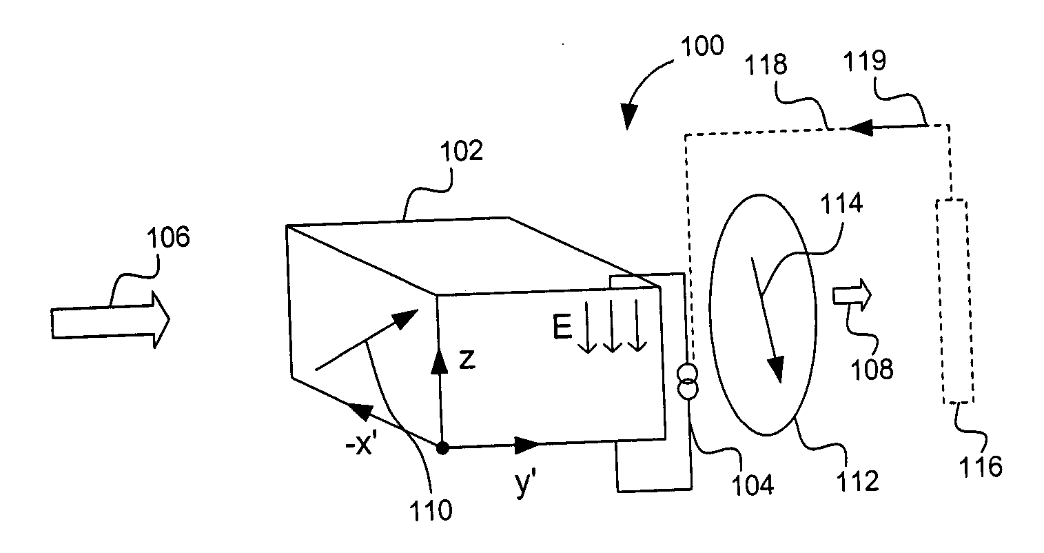
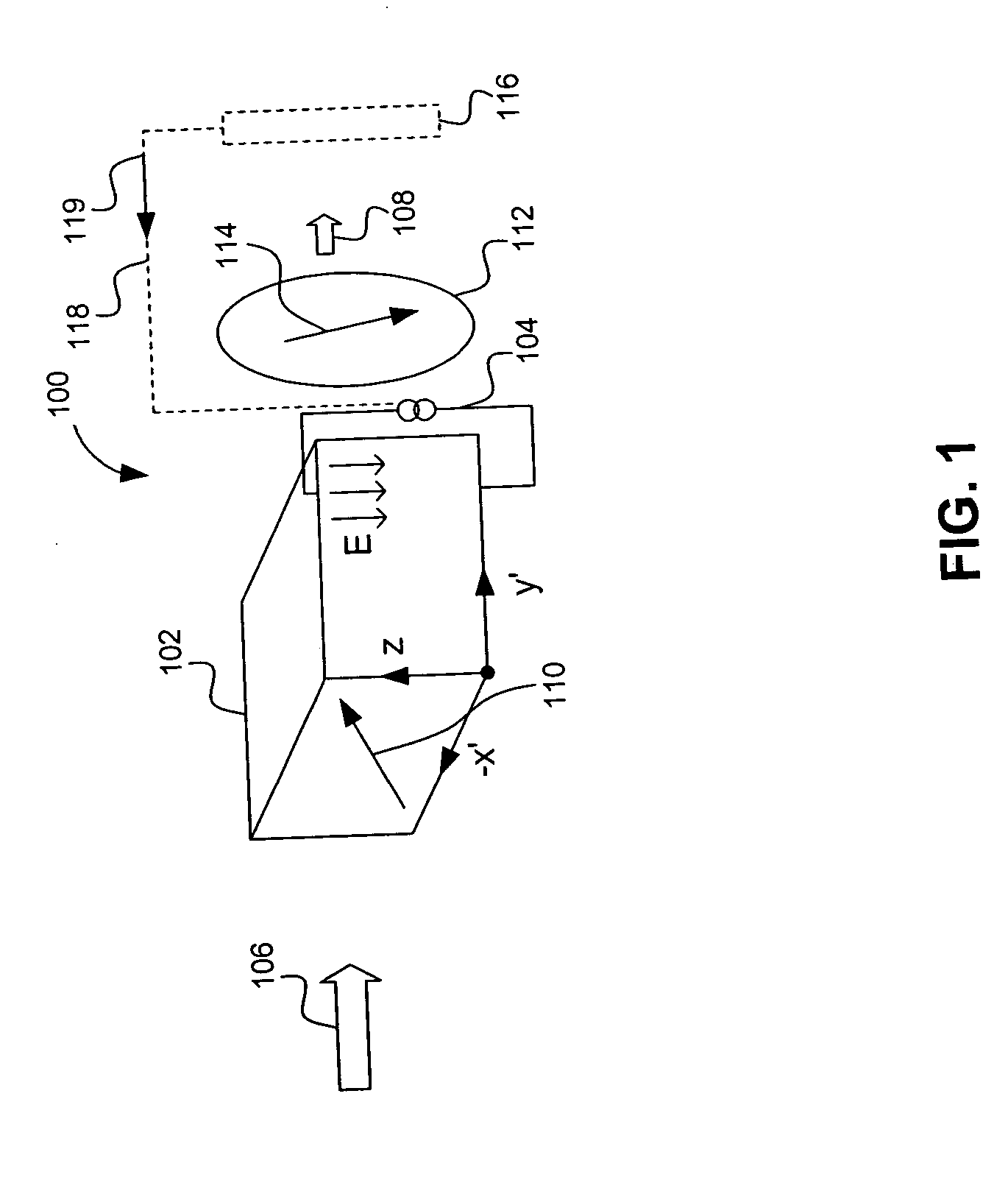
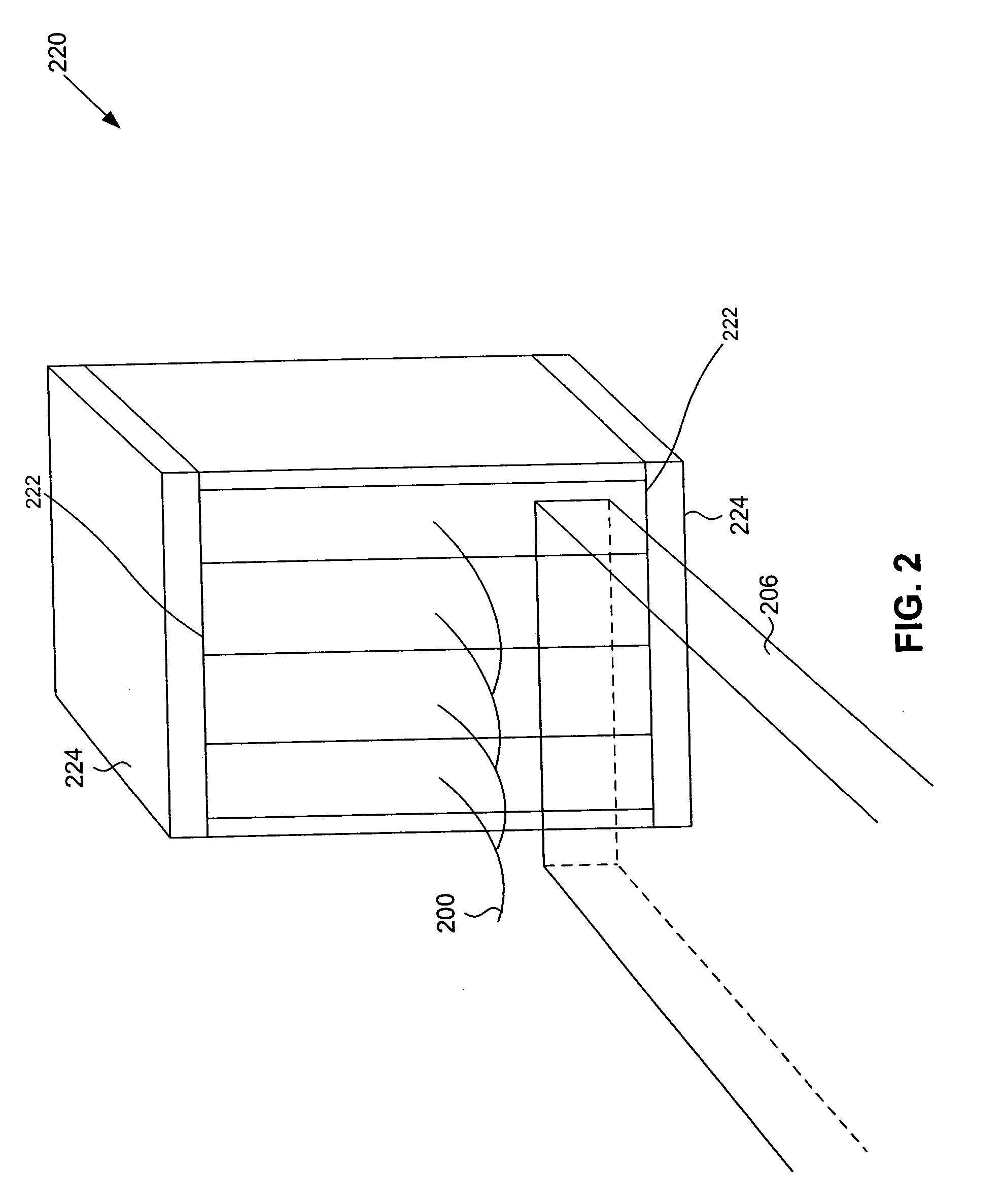
[0028] Embodiments of the present invention provide a system and method utilizing an array of dynamically controllable optical elements that are used to adjust one or more portions of a beam propagating therethrough. For example, the adjustments can be to change a ratio of horizontally and vertically polarized light in the portions of the beam. The adjustments can be made through application of an appropriate electric field to each of the optical elements, which forms an electrooptic modulator. In one example, a polarizer / ...


PUM

PropertyMeasurementUnit
frequencyaaaaaaaaaa
spatial frequenciesaaaaaaaaaa
areaaaaaaaaaaa

Abstract

A system and method utilize an array of dynamically controllable optical elements to adjust one or more portions of a beam propagating therethrough. For example, the adjustments can be to change a ratio of horizontally and vertically polarized light in the portions of the beam. The adjustments can be made through application of an appropriate electric field to each of the optical elements, which forms an electrooptic modulator. In one example, a polarizer/analyzer is positioned after the array, such that only desired orientations are transmitted. The polarizing provides a desired light intensity profile, which can, for example, make the intensity inform across the beam or be used to partially or fully attenuate (e.g., block) the beam.

Description

CROSS REFERENCE TO RELATED APPLICATIONS [0001] This application is related to U.S. Ser. Nos. 10 / 972,582, filed Oct. 26, 2004, and 11 / 005,222, filed Dec. 7, 2004, which are both incorporated by reference herein in their entireties.BACKGROUND [0002] 1. Field of the Invention [0003] The present invention is related to electrooptic modulators. [0004] 2. Background Art [0005] In a pattern generating environment that patterns an impinging beam of radiation, which is later projected onto an object, controlling characteristics of the illumination beam of radiation and / or the patterned beam is critical. This is because in order to form accurate patterns on the object, the beam and / or the patterned beam have to be precisely controlled. [0006] Generally, patterning systems use static optical systems, which are typically designed and manufactured for each application in order to produce the light beams with desired characteristics. In the static optical system example, when a change in illumina...

Claims


Application Information

Patent Timeline
Patent Type & Authority Applications(United States)
IPC IPC(8): G02F1/01
CPCG03F7/70091G03F7/70566
Inventor GOVIL, PRADEEP K.TSACOYEANES, JAMES G.
Owner ASML HLDG NV
Why Eureka
Try Eureka