Light guide plate for uniformly scattering lights from point light source

a light guide plate and light guide technology, applied in the direction of planar/plate-like light guides, lighting and heating apparatuses, instruments, etc., can solve the problems of increasing material cost, power consumption, assembly complexity, and the possibility of future malfunction, and achieve the effect of widening the incident angl

Active Publication Date: 2006-07-27
RADIANT OPTO ELECTRONICS
View PDF11 Cites 36 Cited by
  • Summary
  • Abstract
  • Description
  • Claims
  • Application Information

AI Technical Summary

Benefits of technology

[0008] The primary purpose of the present invention is to provide a light guide plate that can uniformly scatter lights from point light sources. The light guide plate of the present invention forms diffusing entities on the light entering side of the light guide plate, so that lights emitted form the light sources could have wider incident angles and could uniformly scatter into the light guide plate.

Problems solved by technology

On the other hand, the application of LEDs is more complicated as they are point light sources.
Although adding more LEDs 16 could eliminate dark zones 115, this is not a satisfactory approach as the additional LEDs 16 increase material cost, power consumption, assembly complexity, and the possibility of future malfunctioning.
However the approach has its own problem.
These aligned refracted lights would add to each other to form brighter lights 26, resulting in non-uniform lighting of the light guide plate 2.

Method used


Image

  • Light guide plate for uniformly scattering lights from point light source
  • Light guide plate for uniformly scattering lights from point light source
  • Light guide plate for uniformly scattering lights from point light source

Examples


Embodiment Construction

[0029] The following descriptions are of exemplary embodiments only, and are not intended to limit the scope, applicability or configuration of the invention in any way. Rather, the following description provides a convenient illustration for implementing exemplary embodiments of the invention. Various changes to the described embodiments may be made in the function and arrangement of the elements described without departing from the scope of the invention as set forth in the appended claims.

[0030] In the following, detailed description along with the accompanied drawings is given to better explain preferred embodiments of the present invention. Please note that some parts in the accompanied drawings are not drawn to scale or are somewhat exaggerated. It should be understood that this is for illustrative purpose, and is not intended to limit the present invention in any way.

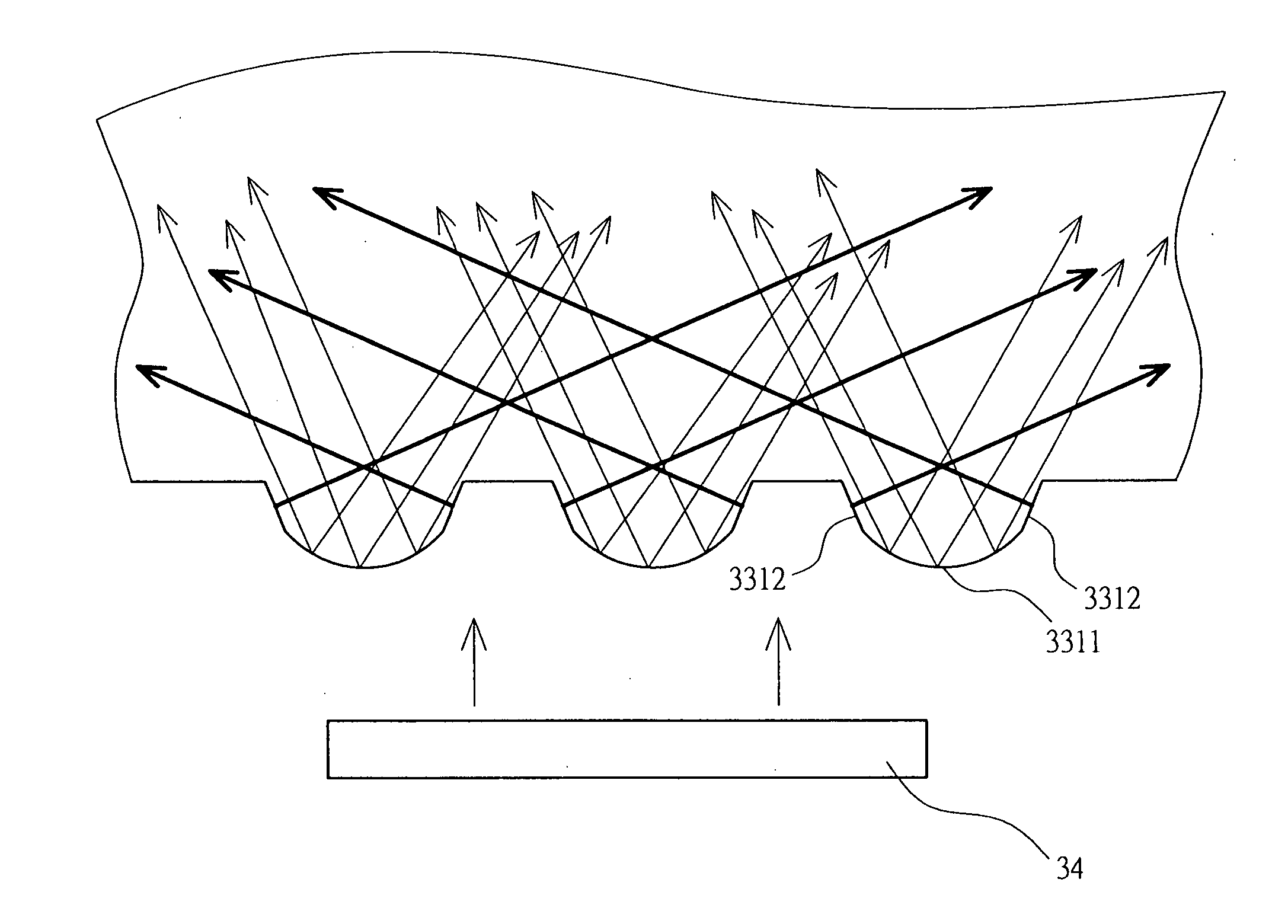
[0031] Please refer to FIG. 6. As shown in FIG. 6, the light guide plate 3 is a transparent board. The light...


PUM


Abstract

A light guide plate that can uniformly scatter lights emitted from point light sources is provided. The light guide plate has a light exiting side, a reflection side opposite to the light exiting side, and a light entering side. On the light entering side, there are multiple miniature diffusing entities. Each of the diffusing entities has a curved surface and two slant surfaces extending from the two ends of the curved surface to the light entering side. The curved surface causes the lights from the light sources to undergo multiple-angled refractions. The two slant surfaces cause the lights from the light sources to undergo fixed-angled refraction in both left and right directions. As such, the lights emitted form the light sources could have wider incident angles and could be uniformly scattered into the light guide plate.

Description

BACKGROUND OF THE INVENTION [0001] (a) Technical Field of the Invention [0002] The present invention generally relates to light guide plates of TFT-LCDs, and more particularly to light guide plates that can uniformly scatter lights from point light sources by widening the lights' incident angles. [0003] (b) Description of the Prior Art [0004] A typical planar light source found in a TFT-LCD, as shown in FIG. 1, mainly includes a light guide plate 11, a reflection plate 12, a number of diffusion films 13 and prism sheets 14, and lamps 15. As one of the most important components of the planar light source 1, the light guide plate 11 receives, transmits, and redirects lights emitted from the lamps 15. [0005] As shown in FIG. 2, the light guide plate 11 is usually of a rectangular shape, having a light exiting side 111, a reflection side 112 opposite to the light exiting side 111, and at least a light entering side 113 at the flank. The lights emitted from the lamps 15 enter into the li...

Claims


Application Information

Patent Timeline
Patent Type & Authority Applications(United States)
IPC IPC(8): F21V7/04
CPCG02B6/0016G02B6/0038
Inventor CHANG, CHIA-YINTSENG, KUAN-LINGCHEN, KUAN-TUNLIU, WEN-LUNGCHEN, YUNG-JEN
Owner RADIANT OPTO ELECTRONICS
Why Eureka
Try Eureka