Spiral blade having wind guide

a technology of wind guide and spiral blade, which is applied in the direction of wind motors, wind motor combinations, motors, etc., can solve the problems of high manufacturing and assembly costs, low economic feasibility, and high wind loss rate, and achieves increased capacity of wind power turbine units 500, increased acceleration, and increased incidence angles

Active Publication Date: 2021-02-23
SUN SANG KYU
View PDF28 Cites 0 Cited by
  • Summary
  • Abstract
  • Description
  • Claims
  • Application Information

AI Technical Summary

Benefits of technology

[0012]A wind control blade 31 of a wind guide 30 of the present invention forms a 20° wind control blade lateral curved surface gradient angle 32, a 30° wind control blade longitudinal spiral twist angle 33, a 180° wind control blade alignment angle 34, and a 15° wind control blade rear gradient angle 35. In addition, a turbine blade 41 forms a 30° turbine blade lateral curved surface gradient angle 42, a 40° turbine blade longitudinal spiral twist angle 43, and a 120° turbine blade alignment angle 44. The 20° wind control blade lateral curved surface gradient angle 32 and the 30° wind control blade longitudinal spiral twist angle 33 of the wind control blade 31 have more gradual and wider incidence angles than the 30° turbine blade lateral curved surface gradient angle 42 and the 40° turbine blade longitudinal spiral twist angle 43 of the turbine blade 41. Accordingly, since more wind enters into the central direction of the inner side of the turbine blade 41 and a primary whirlwind is generated, much higher acceleration can be obtained.
[0013]In addition, a second spiral blade 40 having the same size and shape as the spiral blade 40 and coupled to the rear side of the spiral blade 40 in series increases the capacity of the wind power turbine unit 500 two times without causing temporal and economical burdens, such that a wind pressure can be maintained for a long time. In addition, a rotational force can be increased by reducing a frictional resistance of air behind the spiral blade 40 without interfering with the flow of a fluid.

Problems solved by technology

Extra-large structures require high manufacturing and assembling costs and have low economic feasibility, and in particular, propeller rotary bodies have low air volume integration effects and thus have a high loss rate of winds, and also, have a serious problem of environmental destruction due to damage to nature and noises.
However, air turbulence may be formed due to interference of an air flow between the front rotor and the rear rotor and may rather reduce the speed of winds.
In addition, a ratio between the gears and the rotary shafts of the generator internally connected with each other may be unstable and thus efficiency may be reduced.
The related-art horizontal-axis wind power turbine generator having all power generation devices integrated into the nacelle 1 and driven with the nacelle 1 has many problems that are difficult to solve due to its special space-intensive structure.
Therefore, in the related-art propeller type wind power generator, the blade is less likely to receive winds by itself and thus a utilization rate thereof is low and also, the blade cannot avoid the resistance of the wind behind the blade and thus the rotation speed is low.
Therefore, the overall performance is low.

Method used


Image

  • Spiral blade having wind guide
  • Spiral blade having wind guide
  • Spiral blade having wind guide

Examples


Embodiment Construction

Technical Objects

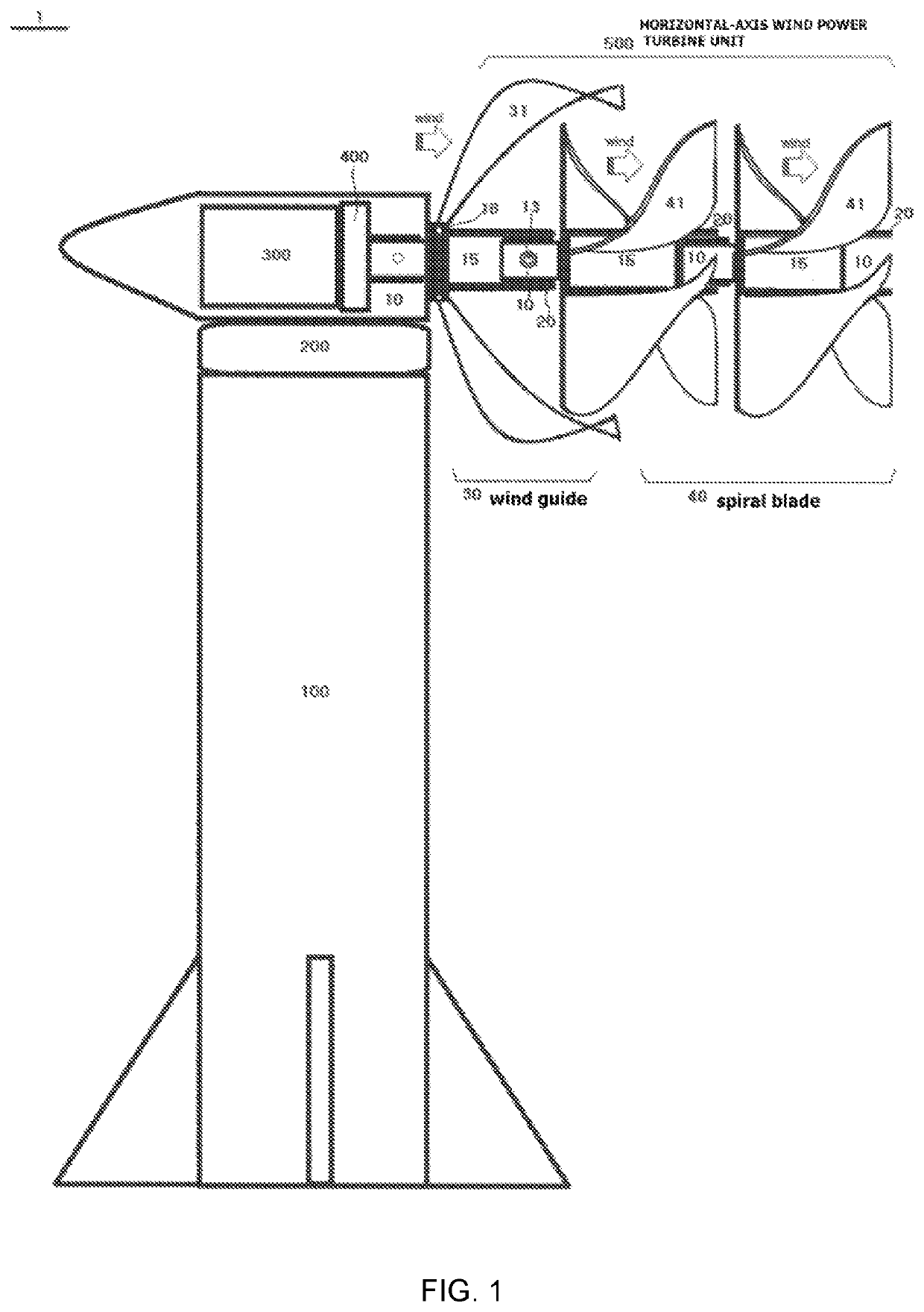
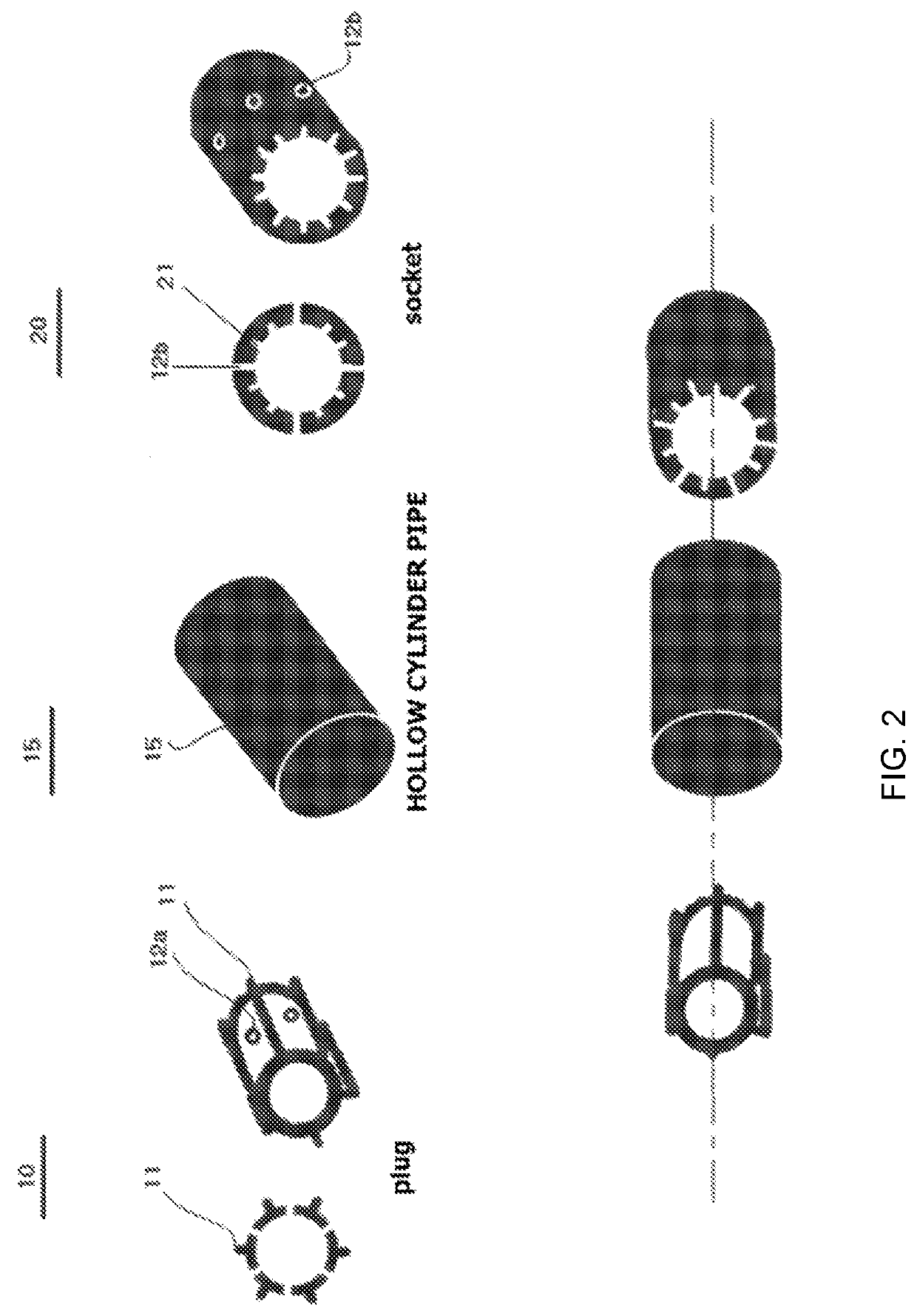
[0009]The present invention has been developed in order to solve the above-described problems of the prior art. An object of the present invention is to provide a wind guide and a spiral blade forming a twist in a longitudinal direction, and provide a horizontal-axis wind power turbine unit using a plug, a socket, and a hollow cylinder pipe.

Technical Solving Means

[0010]The present invention, as the technical idea to achieve the above-described object, includes: a wind guide 30 coupled to the front side of a wind power turbine unit 500 forming a main body; and a spiral blade 40 coupled to the rear side of the wind guide 30.

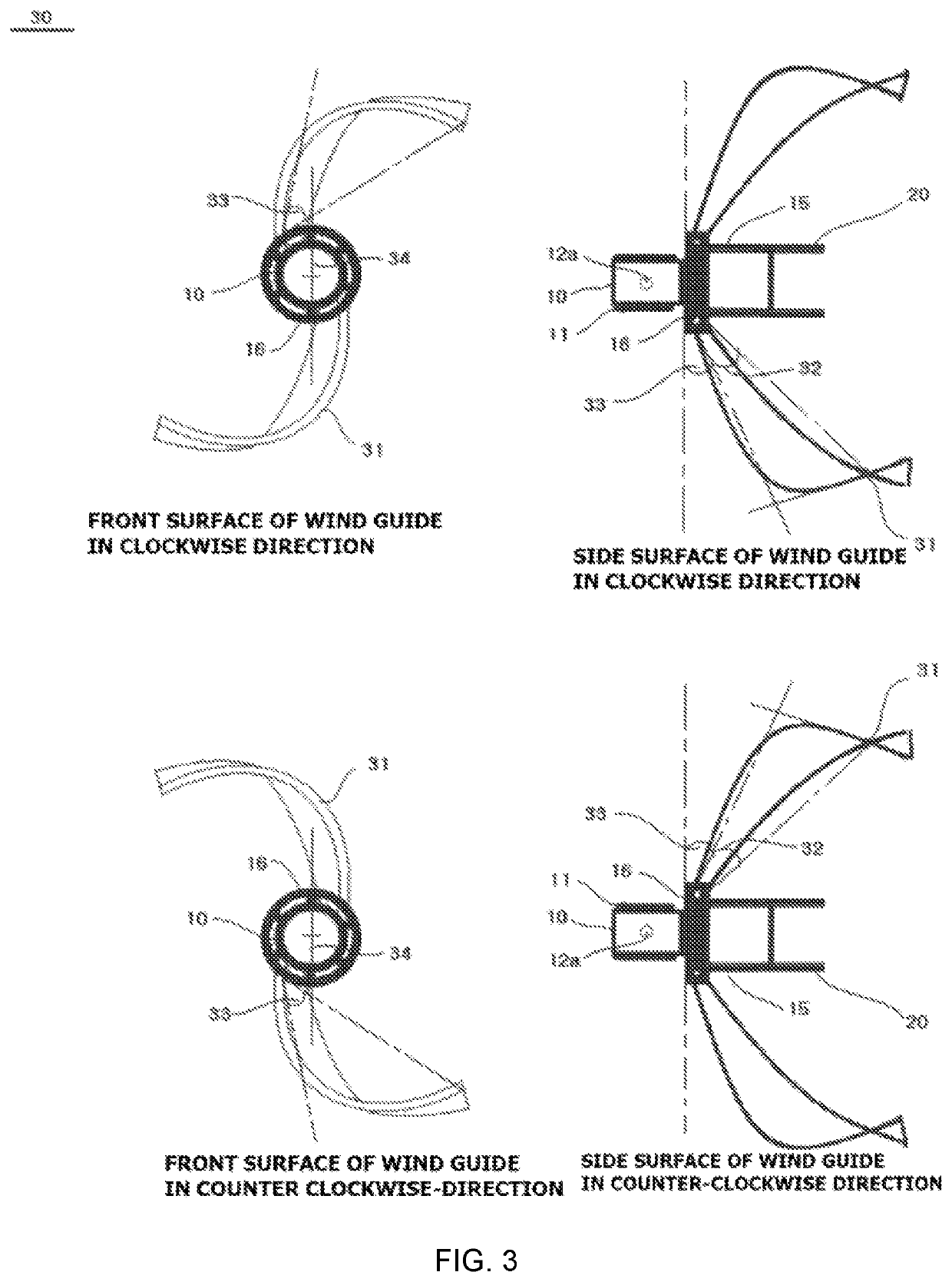
[0011]A wind control blade 31 forms a 20° wind control blade lateral curved surface gradient angle 32, a 30° wind control blade longitudinal spiral twist angle 33, a 180° wind control blade alignment angle 34, and a 15° wind control blade rear gradient angle 35, and a turbine blade 41 forms a 30° turbine blade lateral curved surface gradient angle ...


PUM


Abstract

A wind control blade (31) of a wind guide (30) of the present invention forms a 20° wind control blade lateral curved surface gradient angle (32), a 30° wind control blade longitudinal spiral twist angle (33), a 180° wing control blade alignment angle (34), and a 15° wind control blade rear gradient angle (35). In addition, a turbine blade (41) forms a 30° turbine blade lateral curved surface gradient angle (42), a 40° turbine blade longitudinal spiral twist angle (43), and a 120° turbine blade alignment angle (44). The 20° wind control blade lateral curved surface gradient angle (32) and the 30° wind control blade longitudinal spiral twist angle (33) of the wind control blade (31) have more gradual and wider incidence angles than the 30° turbine blade lateral curved surface gradient angle (42) and the 40° turbine blade longitudinal spiral twist angle (43) of the turbine blade (41). Accordingly, since more wind enters into the central direction of the inner side of the turbine blade (41) and a primary whirlwind is generated, much higher acceleration can be obtained.

Description

CROSS REFERENCE TO RELATED APPLICATIONS[0001]This application is a U.S. National Stage of International Application No. PCT / KR2015 / 012758, filed Nov. 26, 2015, which claims the benefit of Korean patent Application No. 10-2014-0166101, filed Nov. 26, 2014, the entire contents and disclosures of which are incorporated herein by reference.TECHNICAL FIELD[0002]The present invention relates to a spiral blade having a horizontal-axis wind guide for a wind power turbine, and more particularly, to obtaining a rotational force from a wind using a horizontal-axis wind power turbine.BACKGROUND ART[0003]Most of the currently used horizontal-axis wind power turbines aim at using characteristics of winds most efficiently.[0004]Such a wind power turbine generator has a structure of transmitting a rotational force of a rotor installed in parallel with a wind direction to a power generation device via a gear device and a speed change device. Extra-large structures require high manufacturing and asse...

Claims


Application Information

Patent Timeline
Patent Type & Authority Patents(United States)
IPC IPC(8): F03D1/06F03D1/02F03D1/04F03D9/25
CPCF03D1/0625F03D1/025F03D1/04F03D1/0633F03D9/25Y02E10/72F03D1/06
Inventor SUN, SANG KYU
Owner SUN SANG KYU
Why Eureka
Try Eureka