Method and system for controlling bandwidth allocation

Active Publication Date: 2006-07-27
INTEL GERMANY GMBH & CO KG
View PDF14 Cites 24 Cited by
  • Summary
  • Abstract
  • Description
  • Claims
  • Application Information

AI Technical Summary

Benefits of technology

[0015] The terms “register” and RAM memory are used here, as is conventional in this art, to be different from each other and such that a reg

Problems solved by technology

In implementation terms, a RAM memory is

Method used


Image

  • Method and system for controlling bandwidth allocation
  • Method and system for controlling bandwidth allocation

Examples


Embodiment Construction

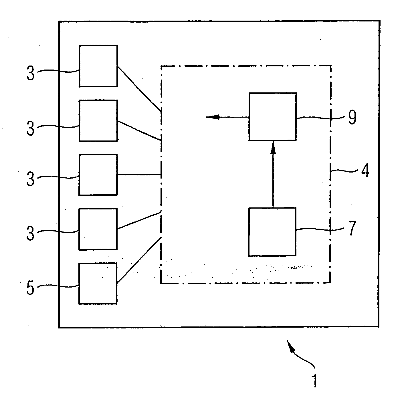
[0019] Referring to FIG. 1 an embodiment of the invention is shown which is an Ethernet switch 1, having a plurality of MAC ingress / egress ports 3 connected to user devices (which may be located within a single building, for example). Port 5 is an ingress / egress port connected to an external communication network such as the Internet.

[0020] The Ethernet switch further includes a control section 4 having a flow engine 7 for examining packets passing through the Ethernet switch and determining which “flow” they belong to, in other words which of the ports 3, 5 they come from and which of the ports 3, 5 they are directed to. Note that optionally any one or more of the flows may be associated, to form groups of flows. For example, the flows from a given one of the ports 3 to the port 5 and from the port 5 to the same port 3 may be associated in this way. In this case, the flow engine 7 may, rather than deciding the exact flow to which the packet belongs, determine only which group of f...


PUM


Abstract

A Ethernet switch 1 includes a monitoring unit 9 for policing the amount of traffic on each of a plurality of flows or groups of flows. The monitoring unit has a memory, implemented in hardware as a RAM memory, having a section of each of the flows or groups of flows, and acting as a token bucket for those flows or group of flows.

Description

RELATED APPLICATIONS [0001] The present rule is a group of five patent applications having the same priority date. Application PCT / SG02 / ______ relates to an switch having an ingress port which is configurable to act either as eight FE (fast Ethernet) ports or as a GE (gigabit Ethernet port). Application PCT / SG02 / ______ relates to a parser suitable for use in such as switch. Application PCT / SG02 / ______ relates to a flow engine suitable for using the output of the parser to make a comparison with rules. The present application relates to monitoring bandwidth consumption using the results of a comparison of rules with packets. Application PCT / SG02 / ______ relates to a combination of switches arranged as a stack. The respective subjects of the each of the group of applications have applications other than in combination with the technology described in the other four applications, but the disclosure of the other applications of the group is incorporated by reference.FIELD OF THE INVENTIO...

Claims


Application Information

Patent Timeline
IPC IPC(8): H04J1/16H04L47/20H04L47/21
CPCH04L47/10H04L47/20H04L47/215H04L49/351H04L49/503
Inventor MISHRA, SHRIDHAR MUBARAQPANDEY, PRAMOD KUMARARDHANARI, GURUPRASAD
Owner INTEL GERMANY GMBH & CO KG
Why Eureka
Try Eureka