Method for reducing cupping artifacts in cone beam CT image data sets

a technology of image data and cupping artifacts, applied in image enhancement, image analysis, instruments, etc., can solve the problems of insufficient system hardware performance, inability to fully realize viable correction, and insufficient water normalization, etc., to reduce cupping artifacts in cone beam ct image data sets, simple manner, and without large hardware expenditure

Inactive Publication Date: 2006-07-27
SIEMENS AG
View PDF4 Cites 5 Cited by
  • Summary
  • Abstract
  • Description
  • Claims
  • Application Information

AI Technical Summary

Benefits of technology

[0005] An object of the present invention is to provide a method for reducing cupping artifacts in cone beam CT image data sets that can be implemented in a simple manner and without large hardware expenditure.

Problems solved by technology

The physical cause of these artifacts can be, for example, radiation hardening, inadequate water normalization, sub-optimal pre-filtering or sub-optimal truncation correction.
In many cases, however, a viable correction is not entirely possible due insufficient system hardware performance, inadequate subject information or inadequate algorithms, etc.

Method used


Image

  • Method for reducing cupping artifacts in cone beam CT image data sets
  • Method for reducing cupping artifacts in cone beam CT image data sets
  • Method for reducing cupping artifacts in cone beam CT image data sets

Examples


Embodiment Construction

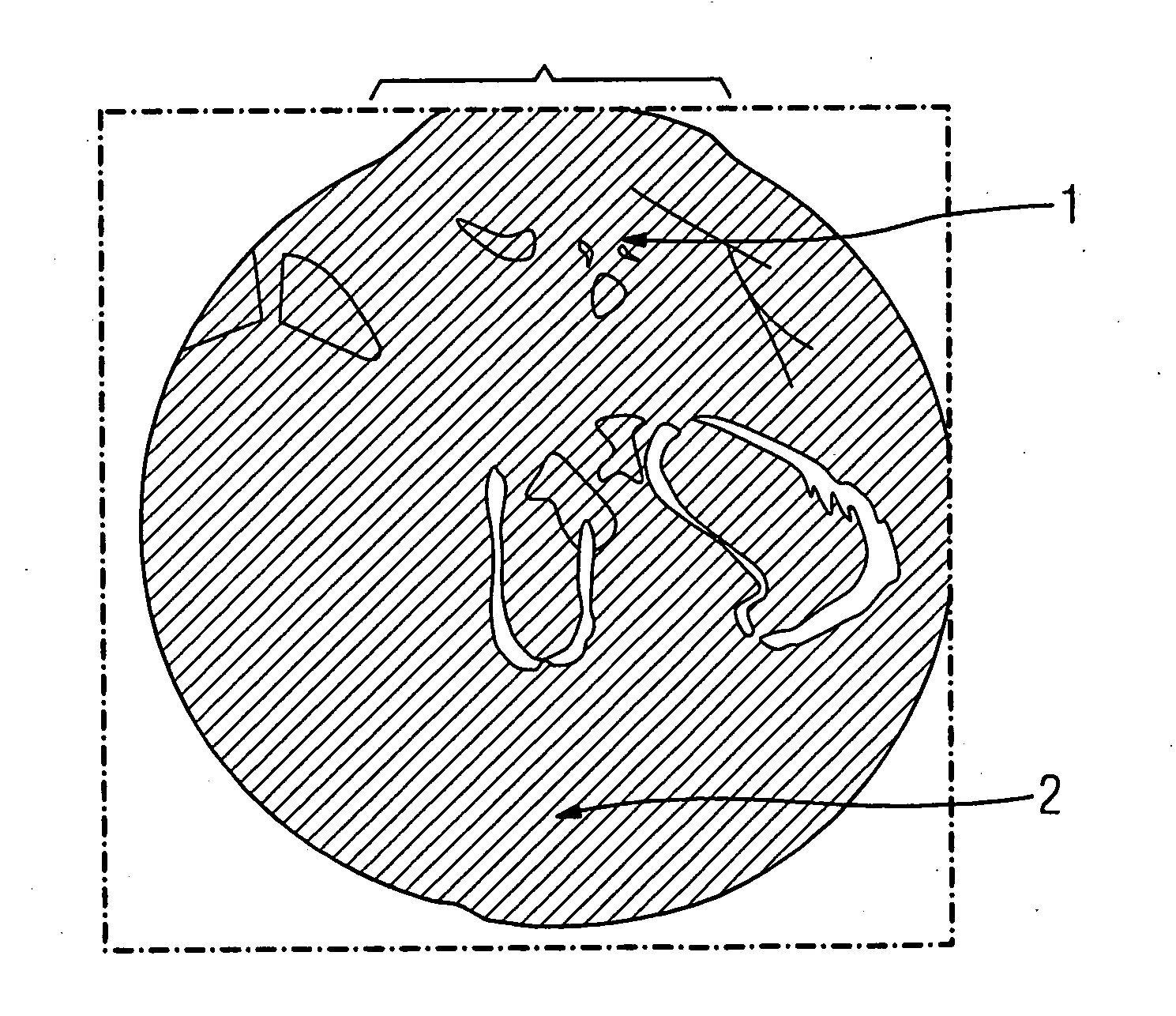
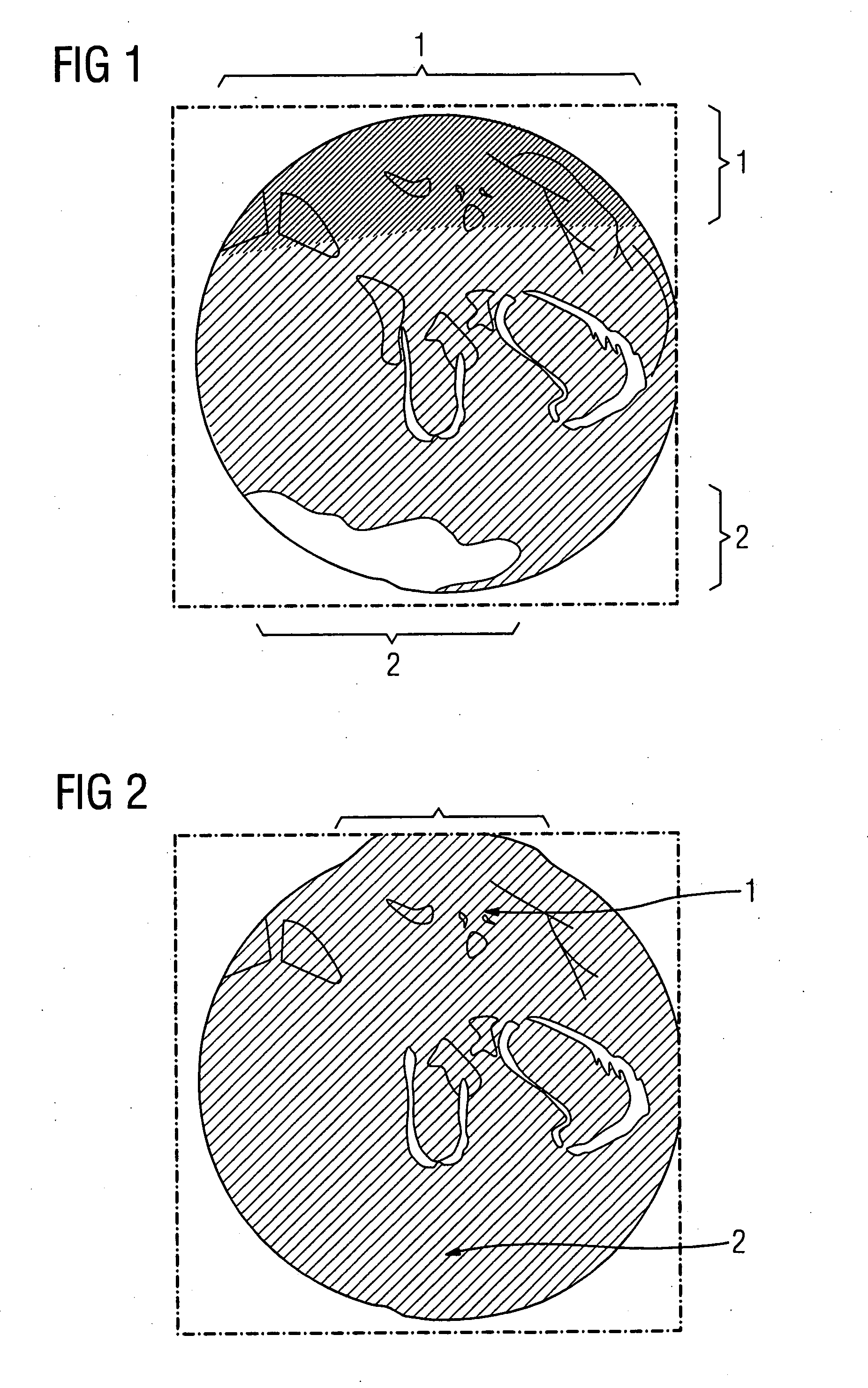
[0011] Two cupping artifacts, namely a darkening of the upper region 1 and a brightening of the lower subject region 2, are present the axial slice of a human pelvic region in FIG. 1. A small windowing to increase contrast is not practically possible in these regions, in particular in the region 2. However, a distinct contrast increase in the cited subject regions 1 and 2 is achieved by the application of a harmonization method (FIG. 2).

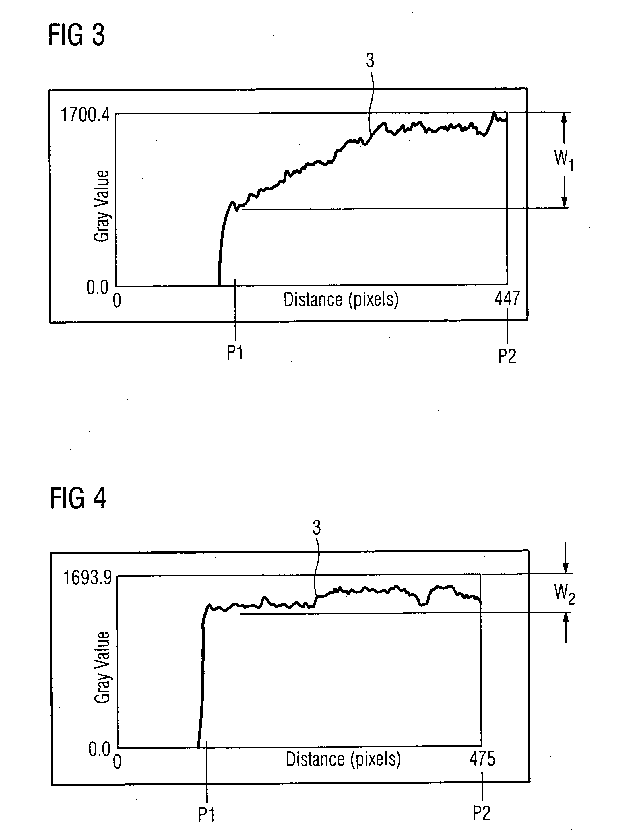
[0012] The cupping artifact of the subject region 2 is explained in FIG. 3 using an image line of an area detector. In the diagram, the removal (in pixels) is plotted on the abscissa and the grey value is plotted on the ordinate. It is clearly seen that a constant component is superimposed on the actual shortwave image signal 3. If it is now desired to spread the subject region or segment of the image line proceeding from the position P1 to the position P2 on the grey level scale of a monitor, only a relatively large grey level window W1 is availabl...


PUM


Abstract

In a method for reduction of cupping artifacts in cone beam CT image data sets, an image data set containing cupping artifacts is electronically processed with a harmonization procedure.

Description

BACKGROUND OF THE INVENTION [0001] 1. Field of the Invention [0002] The present invention concerns a method for reducing cupping artifacts in cone beam CT image data sets. [0003] 2. Description of the Prior Art [0004] In cone beam computed tomography (CT), a fan-shaped x-ray beam is not used, but rather a conical x-ray beam. The reconstruction is based on the technique known as filtered back projection, which is also applied in other CT modalities, for example fan ray CT. Filtered back projection involves a convolution or filter algorithm that significantly influences the image character, for example the spatial resolution and noise. In the back-projection itself, the filtered raw data of the individual 2-D projections are projected back corresponding to their angular position in the image matrix. Conventionally, low-contrast applications (representation of soft tissues) was only conditionally possible. Due to newly developed area detectors and powerful generators, 3-D reconstructio...

Claims


Application Information

Patent Timeline
Patent Type & Authority Applications(United States)
IPC IPC(8): G06K9/00
CPCG06T5/009G06T2200/04G06T2207/10081G06T2207/30004
Inventor FISCHER, DANIELRITTER, DIETER
Owner SIEMENS AG
Why Eureka
Try Eureka