Image compression method and image compression device
a compression method and compression device technology, applied in image enhancement, image analysis, instruments, etc., can solve the problems of limited compression ratio, general irreversible compression, loss of recognition objects in images, etc., and achieve the effect of raising the compression efficiency of images
- Summary
- Abstract
- Description
- Claims
- Application Information
AI Technical Summary
Benefits of technology
Problems solved by technology
Method used
Image

Examples
first embodiment
[0035] First, a first embodiment will be described.
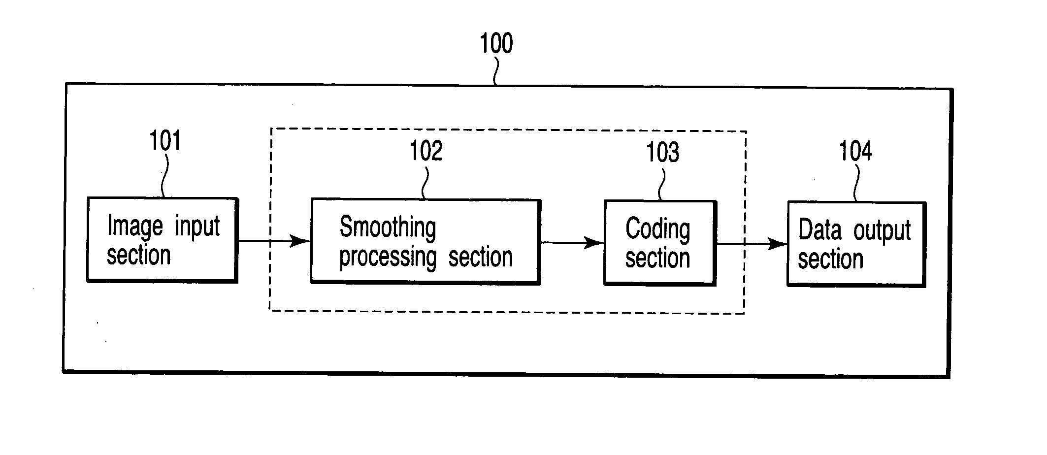
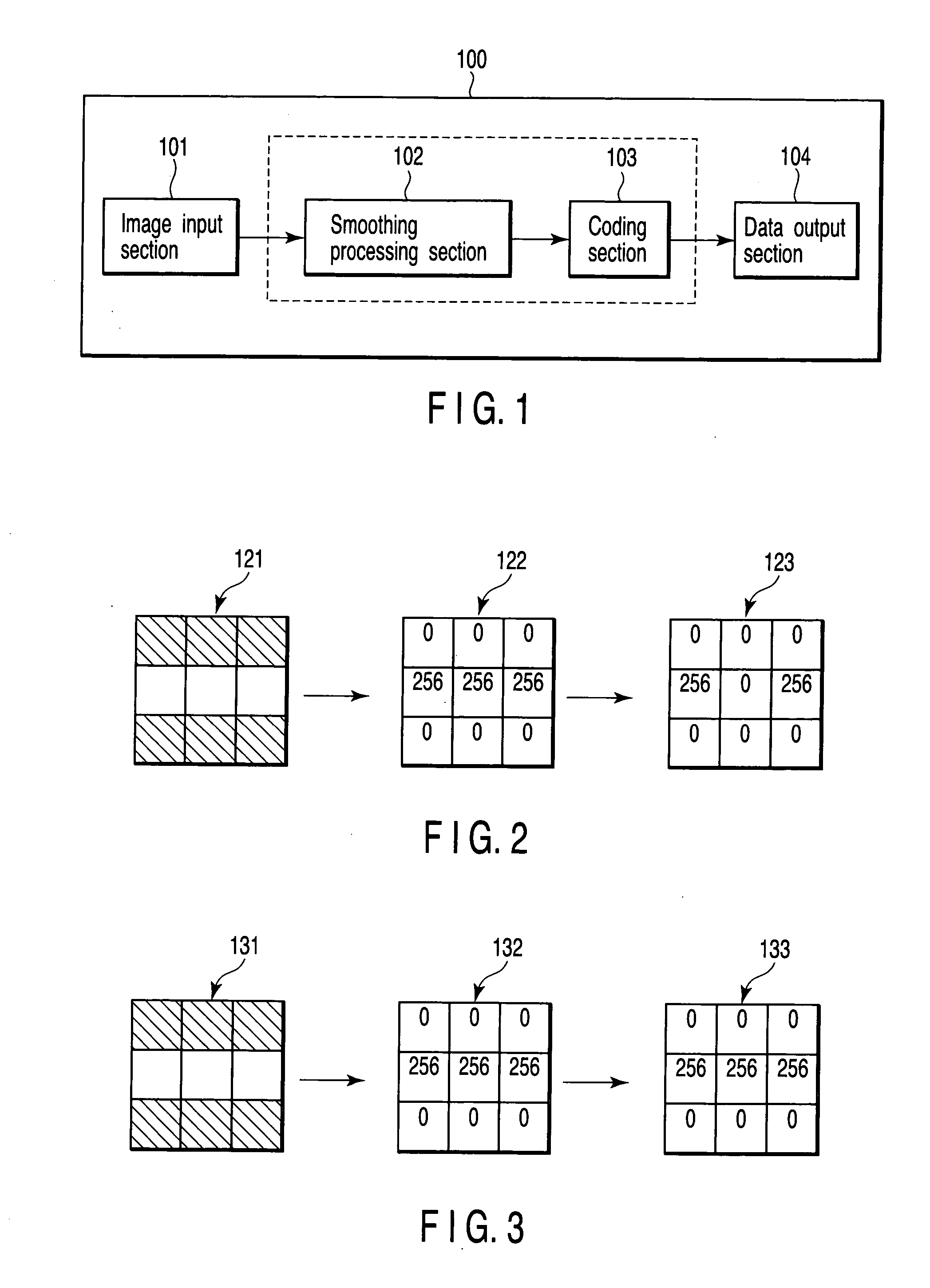
[0036]FIG. 1 schematically shows a constitution example of an image compression device 100 according to a first embodiment.
[0037] According to the first embodiment, as shown in FIG. 1, the image compression device 100 comprises an image input section 101, a smoothing processing section 102, a coding section 103, a data output section 104 and the like.
[0038] The image input section 101 comprises, for example, a digital camera, a television camera, an image scanner or the like. The image input section 101 may input a color image or a monochromatic image. The image input section 101 inputs an image including a recognition object. The image input section 101 supplies the input image to the smoothing processing section 102.
[0039] Moreover, it is assumed that the image input section 101 inputs digital image data in which a value (pixel value) of each pixel is represented by a digital value. For example, the image input section 101 inpu...
second embodiment
[0066] Next, a second embodiment will be described.
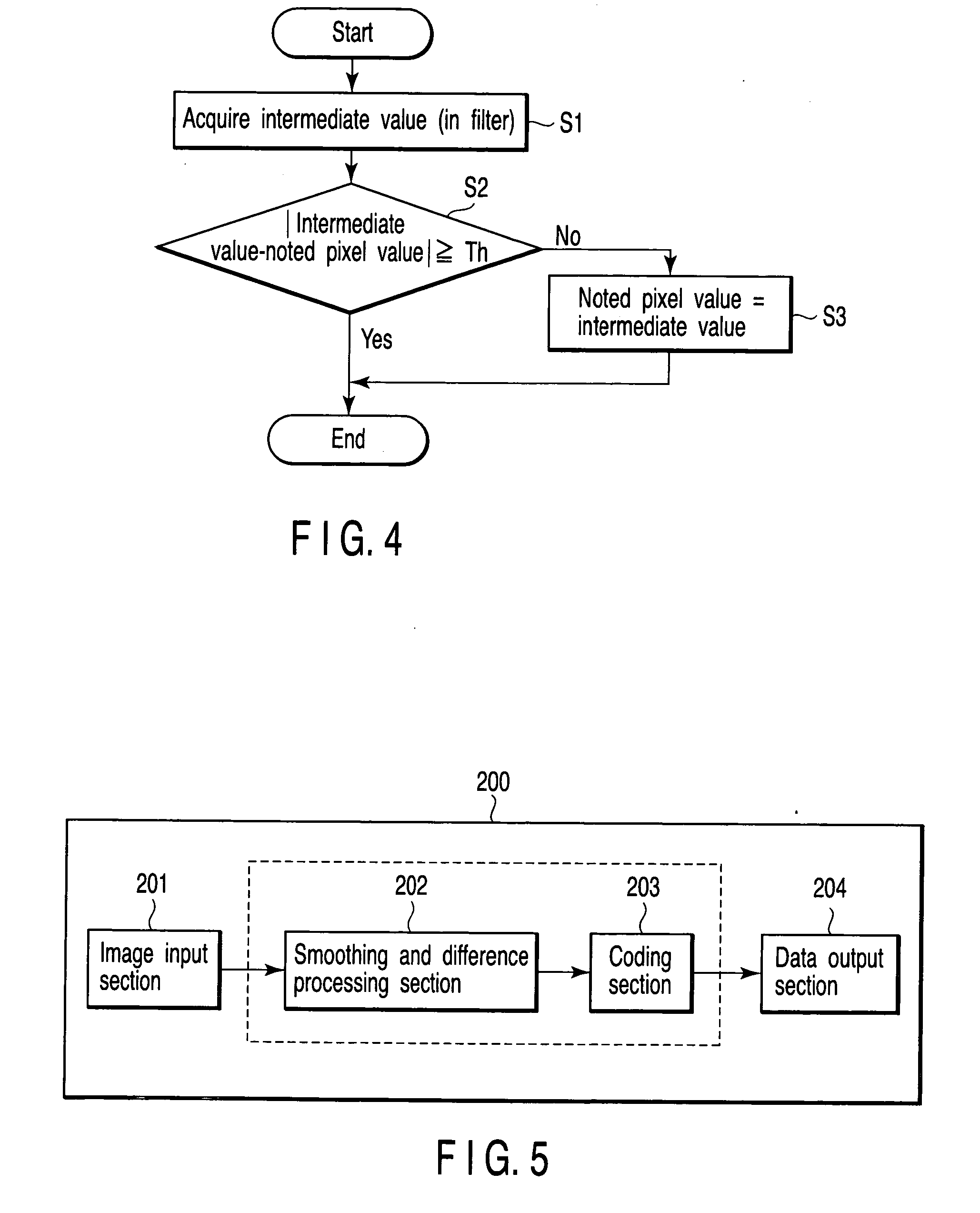
[0067]FIG. 5 schematically shows a constitution example of an image compression device 200 according to the second embodiment.
[0068] The image compression device 200 according to the second embodiment is a modification of the image compression device 100 of the first embodiment. As shown in FIG. 5, the image compression device 200 comprises: an image input section 201; a smoothing and difference processing section 202 as a smoothing processing section and a difference processing section; a coding section 203; a data output section 204 and the like.
[0069] It is to be noted that the image input section 201, the coding section 203, and the data output section 204 are similar to the image input section 101, the coding section 103, and the data output section 104 in the image compression device 100 of the first embodiment. Therefore, detailed description of the image input section 201, coding section 203, and data output section 204 wi...
third embodiment
[0087] Next, a third embodiment will be described.
[0088] This third embodiment will be described mainly assuming a case where a character image is a characteristic which is a recognition object in an image regarded as a compression object.
[0089]FIG. 7 schematically shows a constitution example of an image compression device 300 according to the third embodiment.
[0090] According to the third embodiment, as shown in FIG. 7, the image compression device 300 comprises: an image input section 301; a characteristic extracting section 302; a gradation conversion processing section 303; a coding section 304; a data output section 305 and the like.
[0091] It is to be noted that the image input section 301, the coding section 304, and the data output section 305 are similar to the image input section 101, the coding section 103, and the data output section 104 in the above-described first embodiment. Therefore, detailed description of the image input section 301, coding section 304, and dat...
PUM
 Abstract
Description
Claims
Application Information
 - R&D Engineer
- R&D Manager
- IP Professional
- Industry Leading Data Capabilities
- Powerful AI technology
- Patent DNA Extraction
Browse by: Latest US Patents, China's latest patents, Technical Efficacy Thesaurus, Application Domain, Technology Topic.
© 2024 PatSnap. All rights reserved.Legal|Privacy policy|Modern Slavery Act Transparency Statement|Sitemap