Image forming apparatus

a technology of forming apparatus and forming chamber, which is applied in the direction of electrographic process apparatus, instruments, optics, etc., can solve the problems of jamming around the exit of the fixing section, high temperature exposure, and the inability of the paper discharge roller to discharge the jam easily and safely

Inactive Publication Date: 2006-07-27
KYOCERA DOCUMENT SOLUTIONS INC
View PDF8 Cites 2 Cited by
  • Summary
  • Abstract
  • Description
  • Claims
  • Application Information

AI Technical Summary

Benefits of technology

[0020] With this structure, as the openable section is opened, the paper conveying rollers can be moved into an open position. Thus, if jamming paper is stuck in the conveying nip between the paper conveying rollers, it can

Problems solved by technology

If the paper fails to come off the fixing member, it may jam around the exit of the fixing section and be exposed to a high temperature.
Such a peel-off claw is effective in taking the paper off the fixing member, indeed, but, once the paper jams, the peel-off claw may become an obstacle that interferes with jam disposal.
Here, inconveniently, just on the downs

Method used


Image

  • Image forming apparatus
  • Image forming apparatus
  • Image forming apparatus

Examples


Embodiment Construction

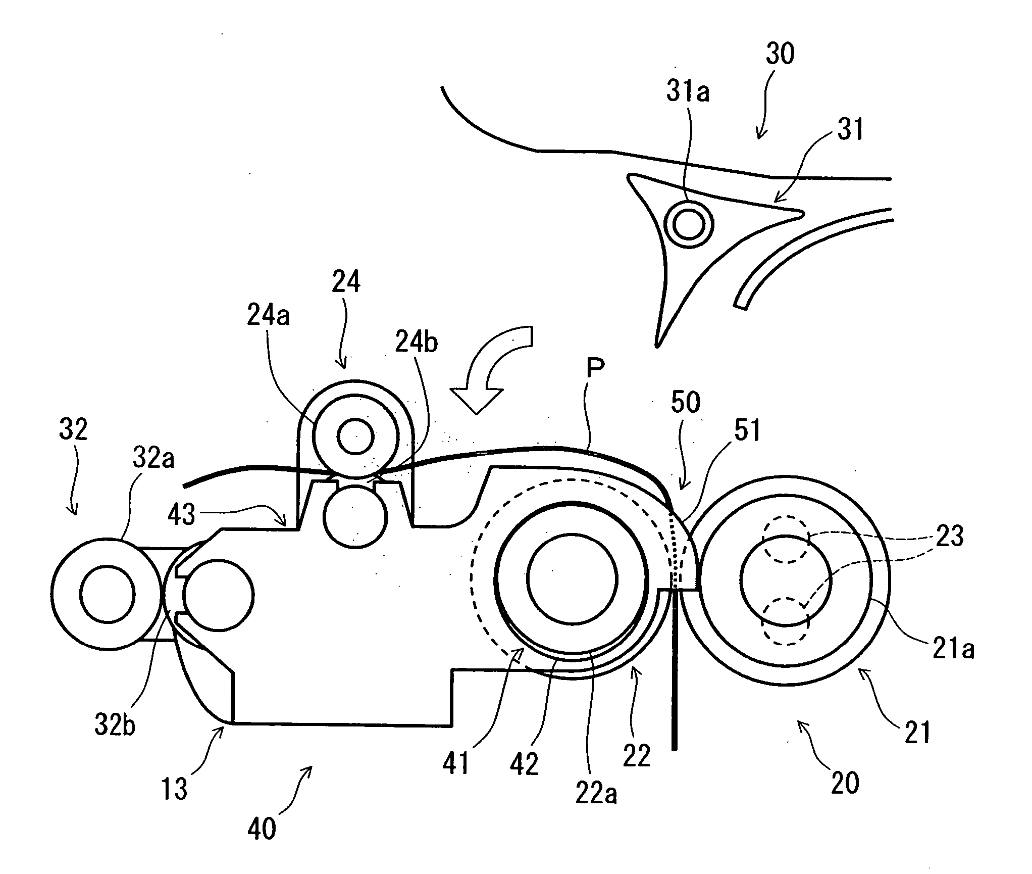
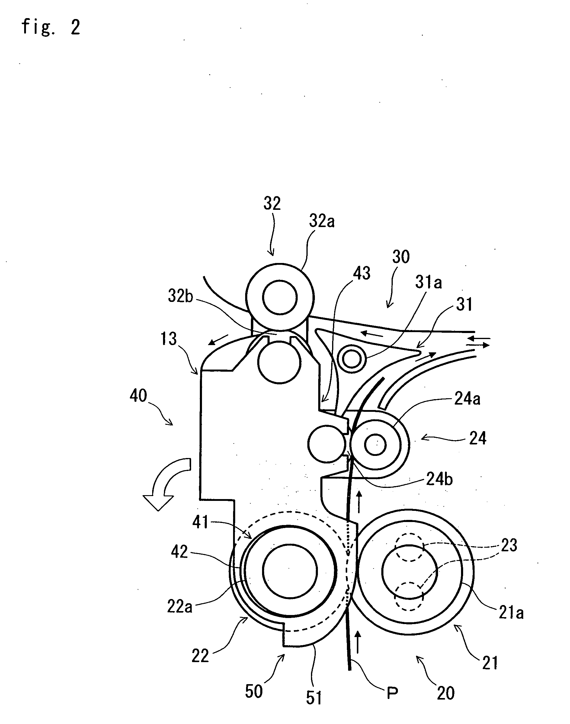
[0025] Hereinafter, an embodiment of the present invention will be described with reference to FIGS. 1 to 4.

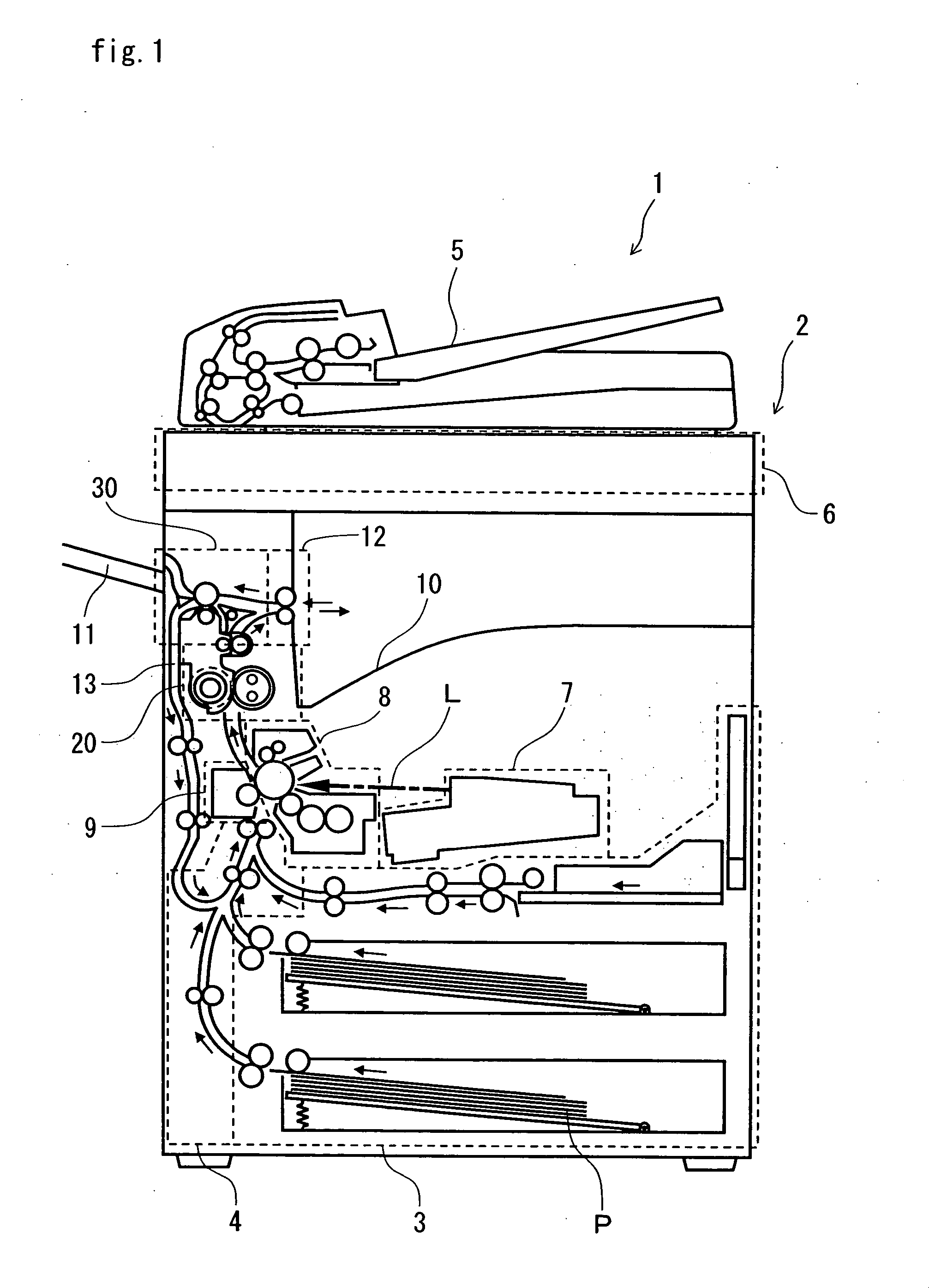
[0026] First, an outline of the construction of an image forming apparatus embodying the present invention, along with the image output operation it performs, will be described with reference to FIG. 1. FIG. 1 is a schematic vertical sectional view, as seen from the front, of the image forming apparatus. In the figure, solid-line arrows indicate the passage through which and the direction in which paper is conveyed, and a dash-and-dot-line arrow represents a laser beam L.

[0027] As shown in FIG. 1, in a lower portion of a body 2 of the image forming apparatus 1, a paper feed section 3 is arranged. Inside the paper feed section 3, unprinted paper P, in the form of stacks of cut sheets, is stocked. From the paper feed section 3, the paper P is fed out one sheet after another.

[0028] Inside the body 2, in a portion thereof on the left of the paper feed section 3, a paper conveyi...


PUM


Abstract

A pair of fixing section discharge rollers 24 is arranged on the downstream side, with respect to the paper conveying direction, of a fixing section 20 including a fixing roller 21 and a pressing roller 22. Near the fixing section 20, a openable section 40 is provided that makes externally accessible the paper conveying passage on the downstream side of the fixing section 20. The openable section 40 has the axis of its pivot portion 41 aligned with the axis of the pressing roller 22, and is rotatable about the pivot portion 41. The fixing section discharge rollers 24 are mounted on the openable section 40. If a paper jam occurs on the downstream side of the fixing section 20, when the openable section 40 is opened, a wide space is secured on the downstream side of the fixing section 20, and the paper P stuck in the conveying nip between the fixing section discharge rollers 24 is automatically brought outward.

Description

[0001] This application is based on Japanese Patent Application No. 2005-016342 filed on Jan. 25, 2005, the contents of which are hereby incorporated by reference. BACKGROUND OF THE INVENTION [0002] 1. Field of the Invention [0003] The present invention relates to an image forming apparatus as exemplified by a copier and a printer. [0004] 2. Description of Related Art [0005] An electrophotographic image forming apparatus such as a copier or a printer incorporates a fixing section, where it fixes a toner image on paper by applying heat and pressure to the paper having the toner image transferred thereto. Heat is applied to the paper by the use of a fixing member such as a fixing roller or a fixing belt. This fixing member is kept in pressed contact with a pressing member such as a pressing roller or a pressing belt so that a fixing nip is formed in between through which to pass the paper to apply pressure thereto. [0006] In the fixing section of the image forming apparatus described ...

Claims


Application Information

Patent Timeline
IPC IPC(8): G03G15/20G03G21/00
CPCG03G2215/00421G03G2215/0043G03G2215/00544G03G2221/1675G03G15/2035
Inventor ITO, HIROSHIHATAKEYAMA, CHISATOISHII, KUNIHIKO
Owner KYOCERA DOCUMENT SOLUTIONS INC
Why Eureka
Try Eureka