Computer-implemented method, system and program product for establishing multiple read-only locks on a shared data object

a technology of shared data and read-only locks, applied in the direction of multi-programming arrangements, program control, instruments, etc., can solve the problems of program execution complete serialization, program cannot exploit the multiple processors, and the performance of thread safe code in applications can suffer

Inactive Publication Date: 2006-07-27
IBM CORP
View PDF6 Cites 43 Cited by
  • Summary
  • Abstract
  • Description
  • Claims
  • Application Information

AI Technical Summary

Benefits of technology

[0048] The changes to the low-level implementation of the read-only locks are transparent to the virtual machine and do not require changes to the “inflated” locks implementation; only the code generated by the JIT compiler at entry and exit to synchronized regions are affected. The pseudo-code below represents the modified reader-lock monitor-enter and monitor-exit algorithms of the present invention: Read-only lock “monitor-enter”:SET Acquired = falseIF FLC == 1 OR INF == 0 THENGOTO virtual machine contended monitor-enter lock pathENDIFIF SharedResource->ThreadID == 0 THENTry atomic increment of the SharedResource->ThreadCountin the sharedresource (object) header wordIF increment succeeded ANDSharedResource->ThreadCount < 256SET Acquired = TRUEENDIFELSEAttempt flat lock acquisitionENDIFIF NOT AcquiredSET FLC = 1GOTO virtual machine contended monitor-enter lock pathENDIFRead-only lock “monitor-exit”:SET SharedResource->ThreadCount =SharedResource->ThreadCount - 1IF SharedResource->ThreadCount = 0IF FLC == 1 THENSET INF = 1SET SharedResource->ThreadID =SystemMonitorAddressGOTO virtual machine contended monitor-exit pathENDIFIF INF == 1 THENGOTO virtual machine contended monitor-exit pathENDIFENDIF
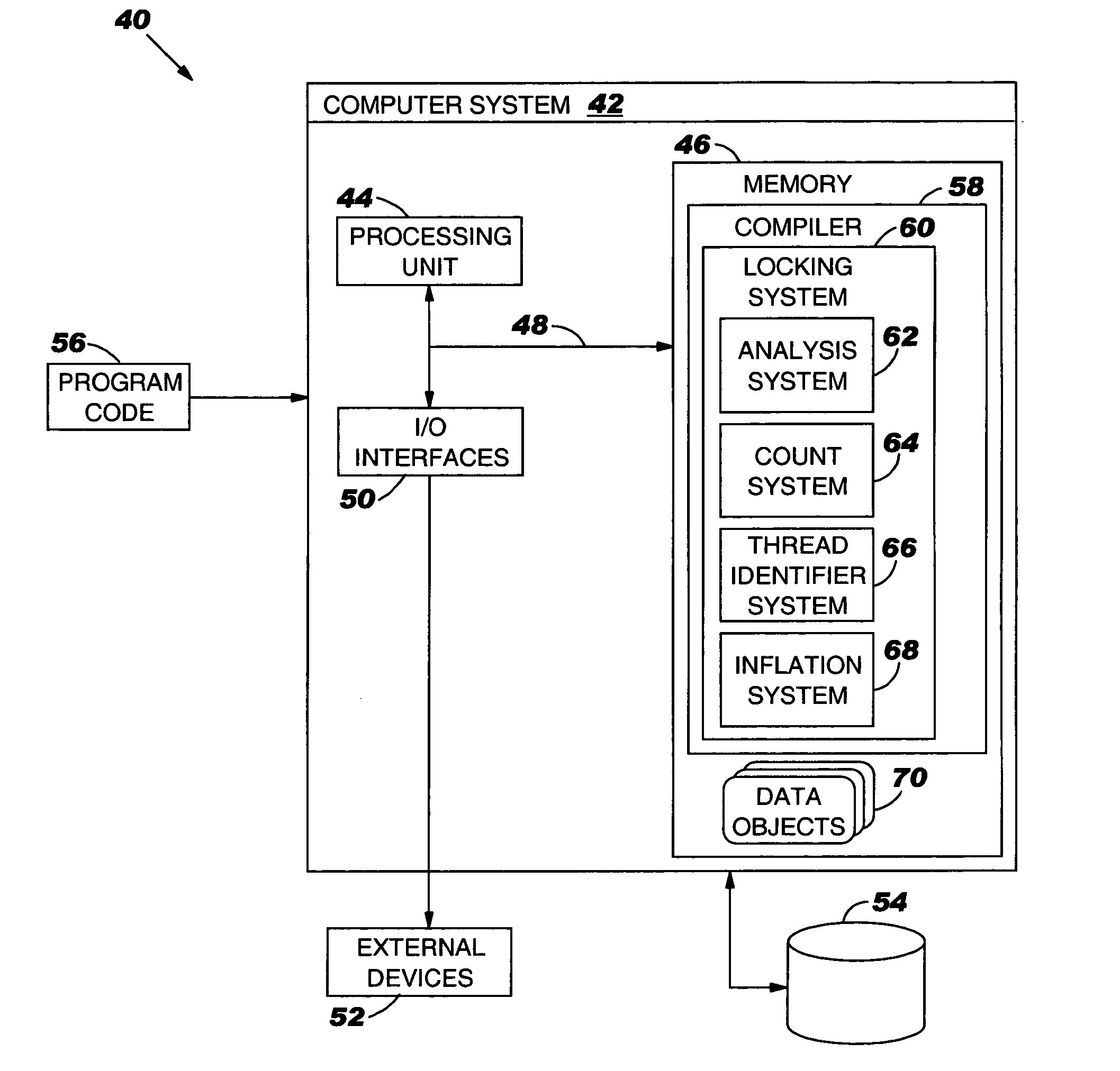
[0049] Referring now to FIG. 4, an illustrative system 40 for permitting / establishing multiple read-only locks (simultaneously) on a shared data object 70 is shown. Specifically, system 40 includes a computer system 42, which could be part of a larger computer infrastructure or environment. In addition, computer system 42 should be understood to be any type of computerized device capable of carrying out the teachings of the present invention. For example, computer system 12 can be a desktop computer, a laptop computer, a hand held device, a client, a server, etc.
[0050] The teachings of the present invention can be implemented via a stand-alone system as shown, or over a network such as the Internet, a local area network (LAN), a wide area network (WAN), a virtual private network (VPN), etc. In the case of the latter, communication throughout the network could occur via a direct hardwired connection (e.g., serial port), or via an addressable connection that may utilize any combination of wireline and / or wireless transmission methods. Conventional network connectivity, such as Token Ring, Ethernet, WiFi or other conventional communications standards could be used. Still yet, connectivity could be provided by conventional IP-based protocol. In this instance, an Internet service provider could be used to establish interconnectivity.
[0051] As further shown, computer system 42 generally includes processing unit 44, memory 46, bus 48, input / output (I / O) interfaces 50, external devices / resources 52 and storage unit 54. Processing unit 44 may comprise a single processing unit, or be distributed across one or more processing units in one or more locations, e.g., on a client and server. Memory 46 may comprise any known type of data storage and / or transmission media, including magnetic media, optical media, random access memory (RAM), read-only memory (ROM), a data cache, a data object, etc. Moreover, similar to processing unit 44, memory 46 may reside at a single physical location, comprising one or more types of data storage, or be distributed across a plurality of physical systems in various forms.
[0052] I / O interfaces 50 may comprise any system for exchanging information to / from an external source. External devices / resources 52 may comprise any known type of external device, including speakers, a CRT, LED screen, hand-held device, keyboard, mouse, voice recognition system, speech output system, printer, monitor / display, facsimile, pager, etc. Bus 48 provides a communication link between each of the components in computer system 42 and likewise may comprise any known type of transmission link, including electrical, optical, wireless, etc.
[0053] Storage unit 54 can be any system (e.g., a database, etc.) capable of providing storage for information under the present invention. As such, storage unit 54 could include one or more storage devices, such as a magnetic disk drive or an optical disk drive. In another embodiment, storage unit 54 includes data distributed across, for example, a local area network (LAN), wide area network (WAN) or a storage area network (SAN) (not shown). Although not shown, additional components, such as cache memory, communication systems, system software, etc., may be incorporated into computer system 42.

Problems solved by technology

The thread safe code in applications can often suffer from performance problems if it is not designed properly.
Therefore if not used properly they can cause complete serialization of the program execution, as if there weren't multiple threads executing, and the program cannot exploit the multiple processors, if they are present on the system.
This is often described as a scalability problem of the application.
In particular, an inconsistent state of a shared data object can exist only if multiple threads are writing to it, or if they are doing reads and writes at the same time.
Unfortunately, implementing such logic under current practices often requires careful engineering and is usually a tedious process, especially where there isn't lightweight support for it in the programming language, as it is the case with Java.

Method used


Image

  • Computer-implemented method, system and program product for establishing multiple read-only locks on a shared data object
  • Computer-implemented method, system and program product for establishing multiple read-only locks on a shared data object
  • Computer-implemented method, system and program product for establishing multiple read-only locks on a shared data object

Examples


Embodiment Construction

[0022] For convenience purposes, the Detailed Description of the Invention will have the following Sections:

[0023] I. General Description

[0024] II. Illustrative Example

[0025] III. Computerized Implementation

I. General Description

[0026] As indicated above, the present invention provides a computer-implemented method system and program product for establishing multiple read-only locks on a shared data objects. Specifically, under the present invention, a locking primitive associated with a shared data object is automatically transformed to allow multiple read-only locks if certain conditions are met. To this extent, when a read-only lock on a shared data object is desired, a thread identifier of an object header lock word (hereinafter “lock word”) associated with the shared data object is examined to determine if a read-write lock on the shared data object already exists. If not, then the thread identifier is set to a predetermined value indicative of read-only locks, and a thre...


PUM


Abstract

Under the present invention, a locking primitive associated with a shared data object is automatically transformed to allow multiple read-only locks if certain conditions are met. To this extent, when a read-only lock on a shared data object is desired, a thread identifier of an object header lock word (hereinafter “lock word”) associated with the shared data object is examined to determine if a read-write lock on the shared data object already exists. If not, then the thread identifier is set to a predetermined value indicative of read-only locks, and a thread count in the lock word is incremented. If another thread attempts a read-only lock, the thread identifier will be examined for the predetermined value. If it is present, the thread count will be incremented again, and a second read-only lock will be simultaneously established.

Description

BACKGROUND OF THE INVENTION [0001] 1. Field of the Invention [0002] In general, the present invention provides a computer-implemented method, system and program product for establishing multiple read-only locks on a shared data object. Specifically, the present invention allows a locking primitive for a shared data object to be automatically transformed to permit multiple read-only locks when certain conditions are met. [0003] 2. Related Art [0004] A program which is executing using multiple threads requires synchronization points to ensure program correctness and proper operation, when two or more threads require access to shared data structures / objects. The synchronization is often achieved using locking primitives on a particular shared data object, where a single thread reserves exclusive access to the object at a given time. All other threads will wait to access the shared data object until the thread which has the access releases the lock, that is, stops using the shared data ...

Claims


Application Information

Patent Timeline
Patent Type & Authority Applications(United States)
IPC IPC(8): G06F9/46
CPCG06F9/526G06F2209/523
Inventor GRCEVSKI, NIKOLASTOODLEY, KEVIN A.STOODLEY, MARK G.SUNDARESAN, VIJAY
Owner IBM CORP
Why Eureka
Try Eureka