Rotatable control lever mount

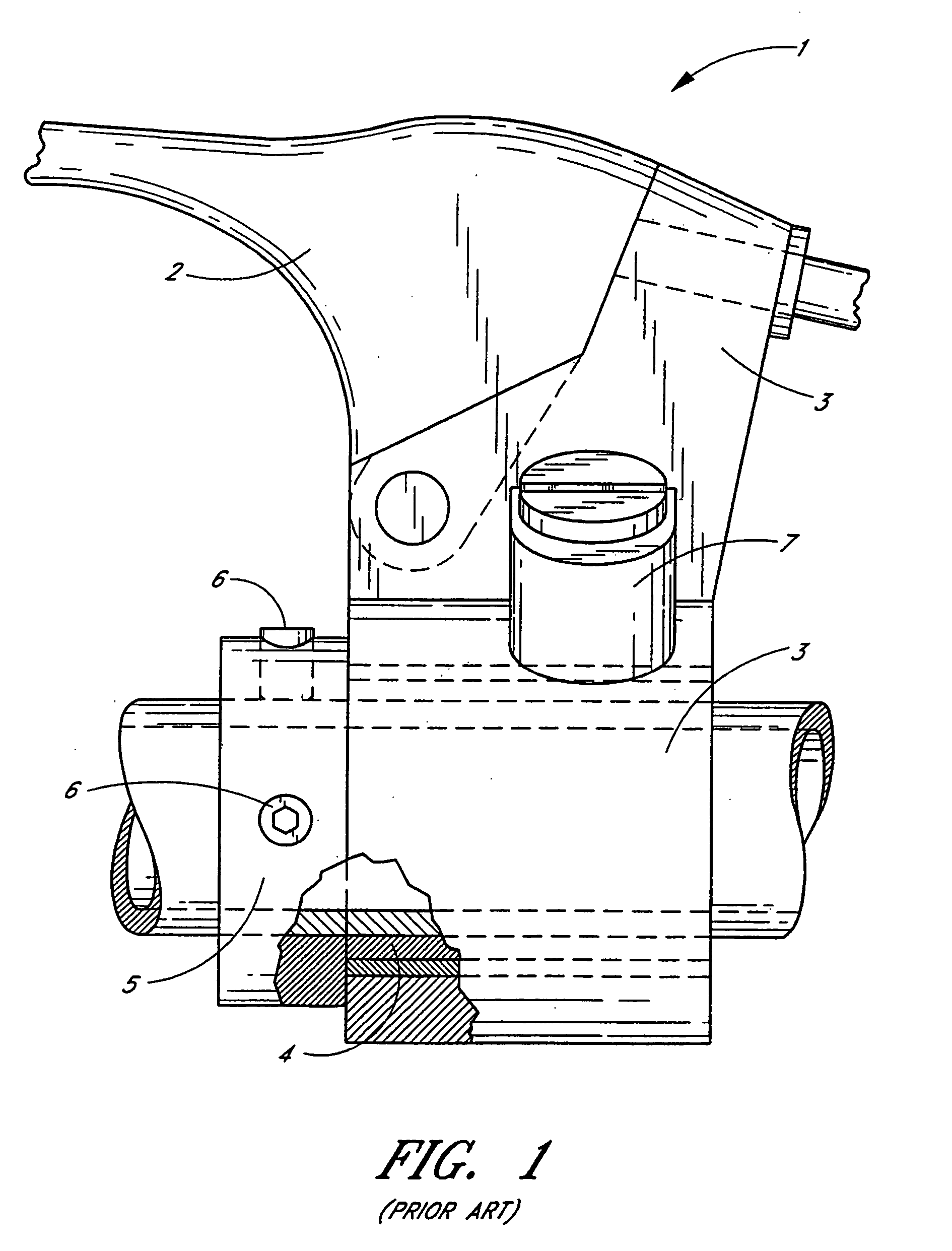
a technology of lever mount and lever, which is applied in the direction of cycle control system, steering device, cycle equipment, etc., can solve the problems of reducing the service life of the myers patent. , to achieve the effect of increasing the diameter of the knurled portion of the handlebar, high friction, and little resistan

Inactive Publication Date: 2006-08-03
BARNETT ROBERT L
View PDF19 Cites 8 Cited by
  • Summary
  • Abstract
  • Description
  • Claims
  • Application Information

AI Technical Summary

Problems solved by technology

While offering some protection to the lever 2 and the lever mount assembly 1, the lever mount 1 of the Myers patent is undesirable in that it allows axial movement of the perch 3.
When the perch 3 moves axially, it may damage other components mounted on the handlebar, such as an engine stop button, for example.
Particularly in the context of racing events, the time necessary to reposition or “reset” the lever perch 3 onto the sleeve 4 renders the Myers lever mount arrangement 1 undesirable.
Further, the sleeve 4 arrangement of the Myers lever mount 1 is likely to be unstable when mounted on a handlebar.
Furthermore, the pressure applied to the handlebar due to the small area of the set screws 6 may damage relatively thin, aluminum handlebars that are presently preferred in motorcycle racing and may render the Myers lever mount 1 unusable with handlebars constructed from other materials, such as composites, for example.

Method used


Image

  • Rotatable control lever mount
  • Rotatable control lever mount
  • Rotatable control lever mount

Examples


Embodiment Construction

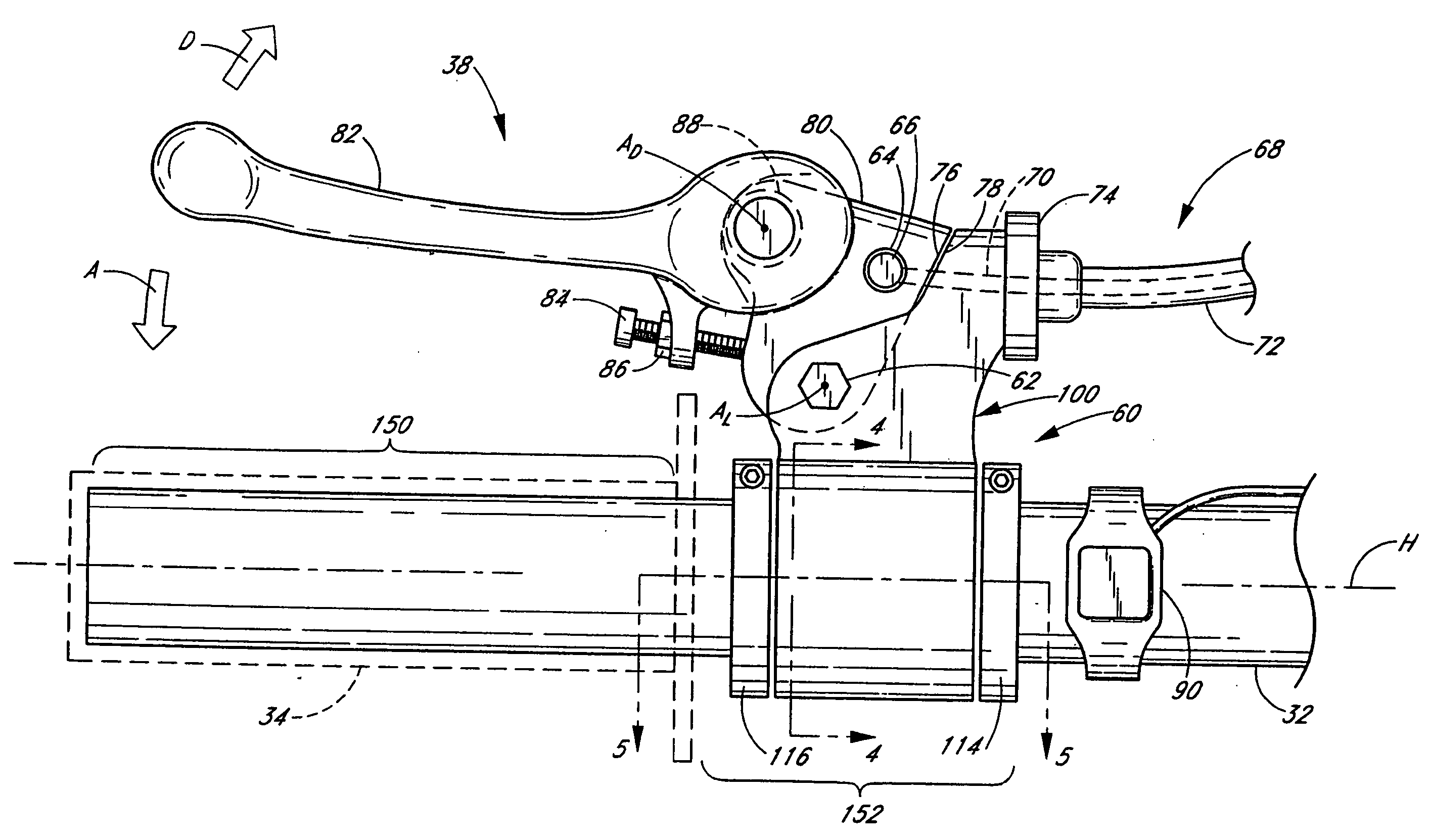
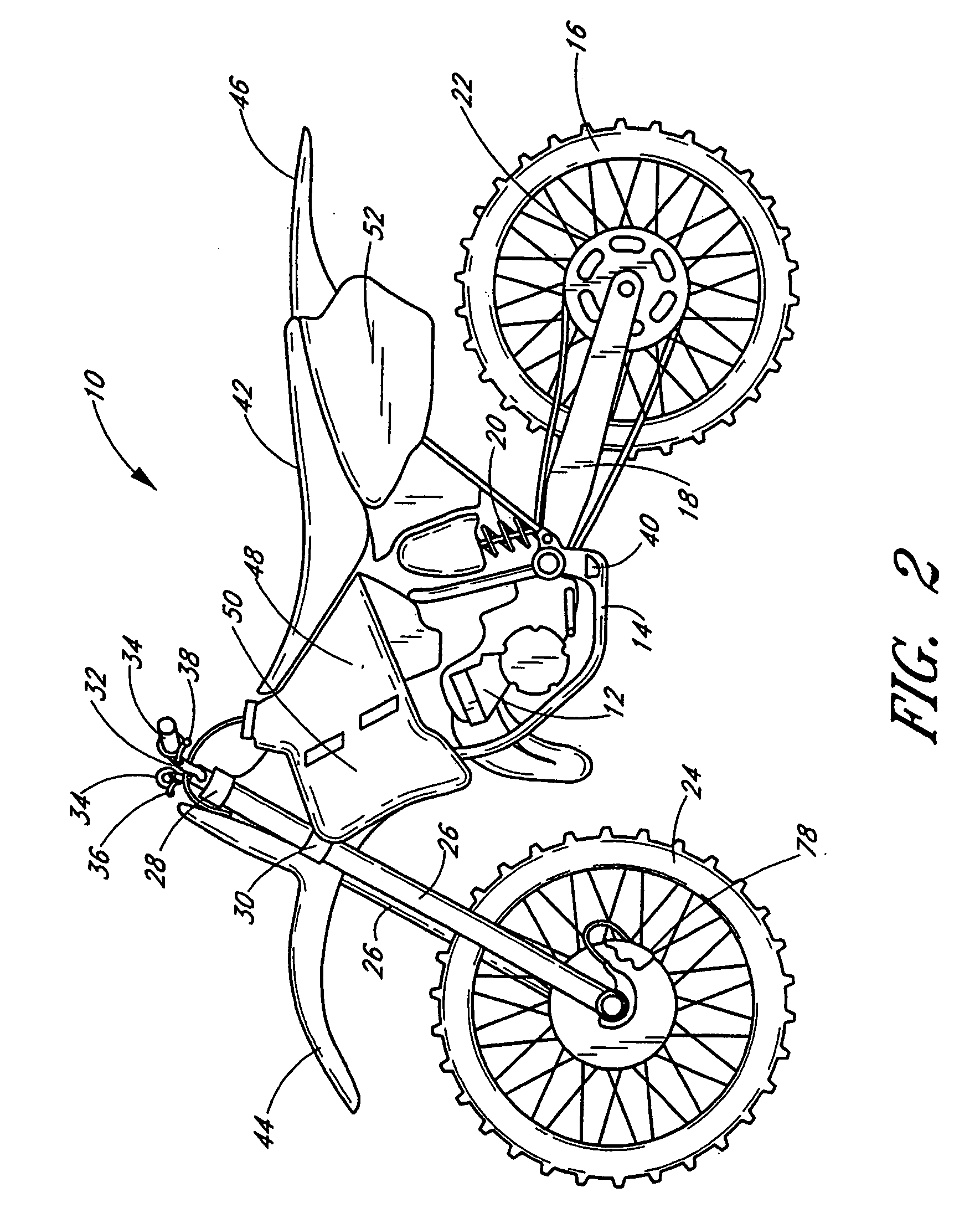
[0028] The present invention finds utility with a number of vehicles, including, without limitation, motorcycles, bicycles, all terrain vehicles (ATVs) and other types of vehicles where control levers may be employed. In addition, advantages present in preferred embodiments may be realized with a number of different control lever functions, such as for use with a manual clutch or braking system, for example. Illustrated embodiments of the control lever mounts, however, are particularly suited for use with a cable-actuated manual clutch lever of an off-road motorcycle.

[0029] With reference to FIG. 2, an off-road motorcycle, generally referred to by the reference numeral 10, is shown. Preferably, an internal combustion engine 12 and associated transmission is mounted within a frame 14 of the motorcycle 10. A rear wheel 16 is connected to the frame through a rear suspension system comprised of a swing arm 18 and a rear shock absorber 20. Preferably, the rear wheel is driven by the eng...


PUM


Abstract

A control lever mount assembly suitable for use in connection with an off-road motorcycle. The lever mount assembly includes a lever-supporting portion, or perch, which is configured to rotatably support a control lever. A sleeve is secured to the handlebar and supports the perch for rotation about an axis of the handlebar. A detent assembly secures the perch in a desired angular orientation relative to the sleeve and the handlebar. The detent assembly is configured to permit rotation of the perch in response to a force being imparted to the lever and / or perch during a crash or fall to protect the perch and lever from damage. In some arrangements, the sleeve may be comprised of two separate pieces.

Description

RELATED APPLICATION [0001] This application is a continuation-in-part of U.S. Patent Application No. ______ (Attorney Docket No. BOBARN.005C1CP1 entitled Rotatable Control Lever Mount), filed Feb. 9, 2006, pending, which is a continuation-in-part of U.S. patent application Ser. No. 11 / 129,879, filed May 16, 2005, abandoned, which is a continuation of U.S. patent application Ser. No. 10 / 138,933, filed May 3, 2002, now U.S. Pat. No. 6,892,603. The entireties of these related applications are hereby incorporated by reference herein and made a part of the present disclosure.BACKGROUND OF THE INVENTION [0002] 1. Field of the Invention [0003] The present invention relates generally to control lever assemblies for operating a control system of a vehicle. More specifically, the present invention relates to a rotatable control lever mount to inhibit breakage of the control lever, especially suited for use with a front brake or a manual clutch system of an off-road motorcycle. [0004] 2. Descr...

Claims


Application Information

Patent Timeline
Patent Type & Authority Applications(United States)
IPC IPC(8): B62K21/12
CPCY10T74/20822B62K23/06
Inventor BARNETT, ROBERT L.
Owner BARNETT ROBERT L
Why Eureka
Try Eureka