Receiver collar

a receiver collar and animal collar technology, applied in the field of animal collar systems, can solve the problems of requiring a level of expertise, unable to reach the target, and unable to test the electrical portions of the animal collar, etc., and achieve the effect of easy testing of the electrical parts of the animal collar

Active Publication Date: 2006-08-03
RADIO SYST CORP
View PDF9 Cites 32 Cited by
  • Summary
  • Abstract
  • Description
  • Claims
  • Application Information

AI Technical Summary

Benefits of technology

[0009] An advantage of the present invention is that the electrical portions of the animal collar are easily tested.
[0010] Another advantage of the present invention is that the voltage level of the battery i

Problems solved by technology

The actual functioning of the collar system can be determined by activating the collar while on the animal, which may have an unintended consequence by applying a stimulus at an inappropriate time.
This approach is normally not feasible due to the time required to disassemble

Method used


Image

  • Receiver collar
  • Receiver collar
  • Receiver collar

Examples


Embodiment Construction

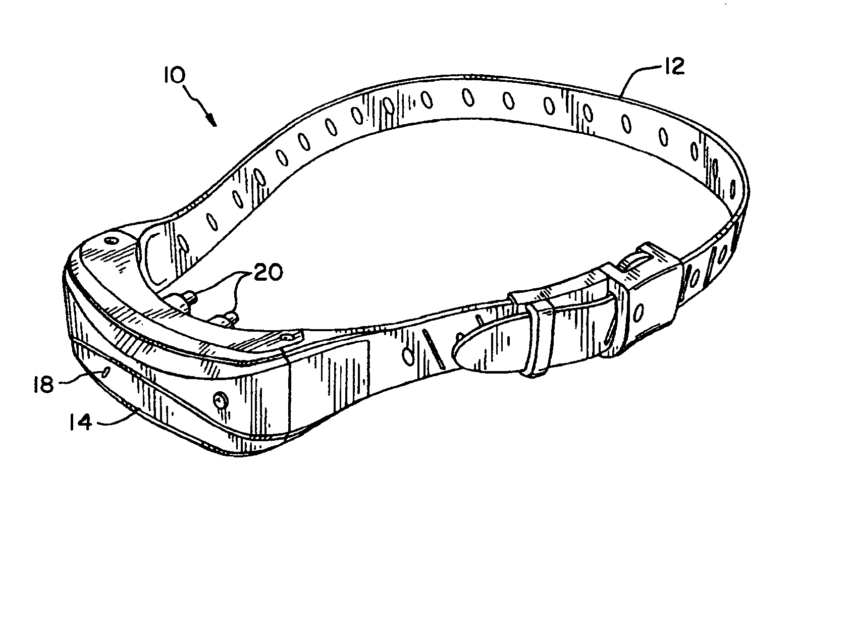
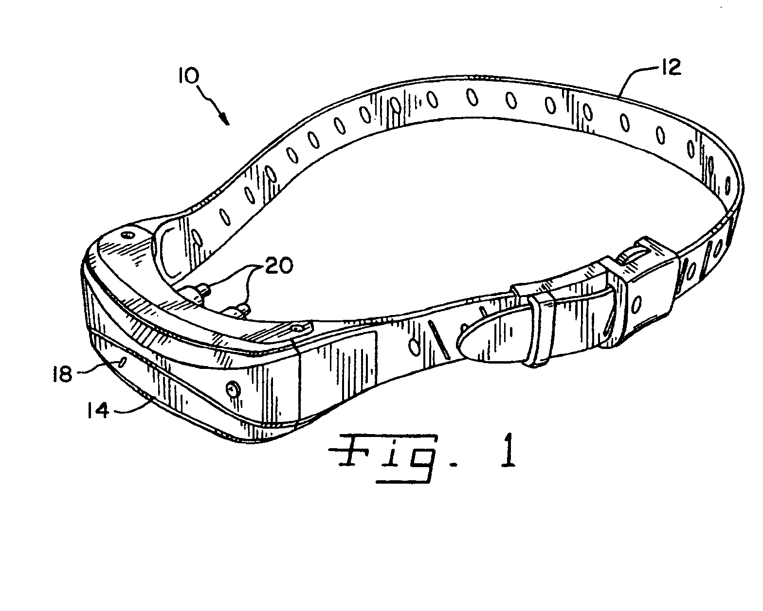
[0017] Referring now to the drawings, and more particularly to FIGS. 1 and 2, there is shown an embodiment of an animal collar system 10 including a collar 12, a housing 14, an electrical circuit assembly 16, a light emitting diode (LED) 18 connected to housing 14 and electrode probes 20 protrude from housing 14. Collar 12 is connected to housing 14 and is adjustable to fit the animal's neck. Housing 14 has an LED 18, which can be in the form of an indicator 18, attached to a portion of housing 14. Indicator 18 may be an audio and / or visual indicator. Housing 14 contains electrical circuit assembly 16, which is electrically connected to electrode probes 20 for the delivery of a stimulus to the neck of the animal that is in contact with electrode probes 20.

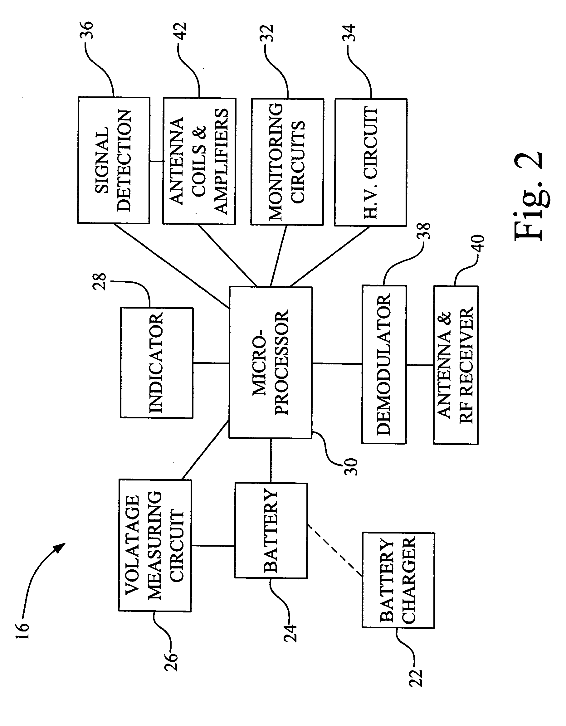
[0018] Electrical circuit assembly 16 is illustrated with a battery charger 22 that is intermittently connected to battery 24 in order to charge battery 24, which is schematically indicated by the dashed line of FIG. 2. Electrical...


PUM


Abstract

An animal collar system including an animal collar, a housing mounted to the animal collar and an electrical circuit. The electrical circuit is enclosed in the housing and a built-in-test circuit is electrically connected to the electrical circuit.

Description

CROSS REFERENCE TO RELATED APPLICATIONS [0001] This is a non-provisional application based upon U.S. provisional patent application Ser. No. 60 / 648,178, entitled “SYSTEM BUILT IN TEST FOR ANIMAL CORRECTION RECEIVER COLLARS”, filed Jan. 28, 2005.BACKGROUND OF THE INVENTION [0002] 1. Field of the Invention [0003] The present invention relates to an animal collar system, and, more particularly to an animal collar system including a receiver for the modification of animal behavior. [0004] 2. Description of the Related Art [0005] Stimulation devices are used for the modification of behavior of an animal. The stimulation device is often associated with a collar worn by the animal and is provided to improve the behavior of the animal. Some stimulation devices include twin electrodes that are positioned against the skin of an animal, which delivers an electrical stimulus to modify the behavior of the animal. The stimulus can also be in the form of a vibration, an audible tone or noise, or o...

Claims


Application Information

Patent Timeline
IPC IPC(8): A62B35/00
CPCA01K15/021A01K27/009G08B5/004G08B7/06
Inventor GERIG, DUANE A.
Owner RADIO SYST CORP
Why Eureka
Try Eureka