
Axle arrangement for a vehicle

Inactive Publication Date: 2006-08-03
CHRYSLER MOTORS CORP
View PDF12 Cites 15 Cited by
  • Summary
  • Abstract
  • Description
  • Claims
  • Application Information

AI Technical Summary

Problems solved by technology

Often, in off-road maneuvering such as on trails or at a construction site, obstacles are encountered that require a tight turning radius to be able to maneuver around or avoid the obstacle.
The centrally mounted rear differential typically reduces ground clearance and the solid rear axle results in an upward rotative force being applied to one rear tire while a downward rotative force is applied to the other rear tire.
Though the previously described vehicle configurations and powertrain systems work for their intended purpose, they also possess certain attributes that detract from their overall utility.

Method used


Image

  • Axle arrangement for a vehicle
  • Axle arrangement for a vehicle
  • Axle arrangement for a vehicle

Examples


case 200

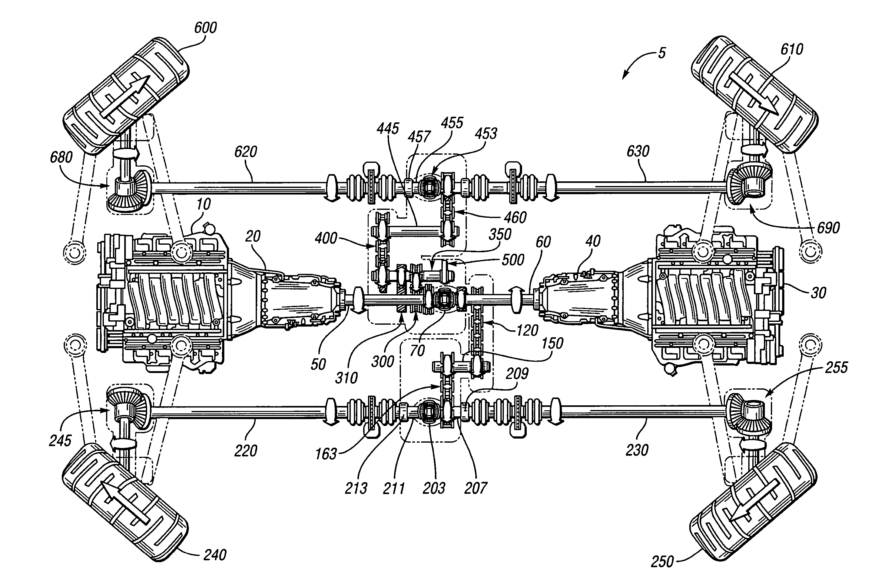
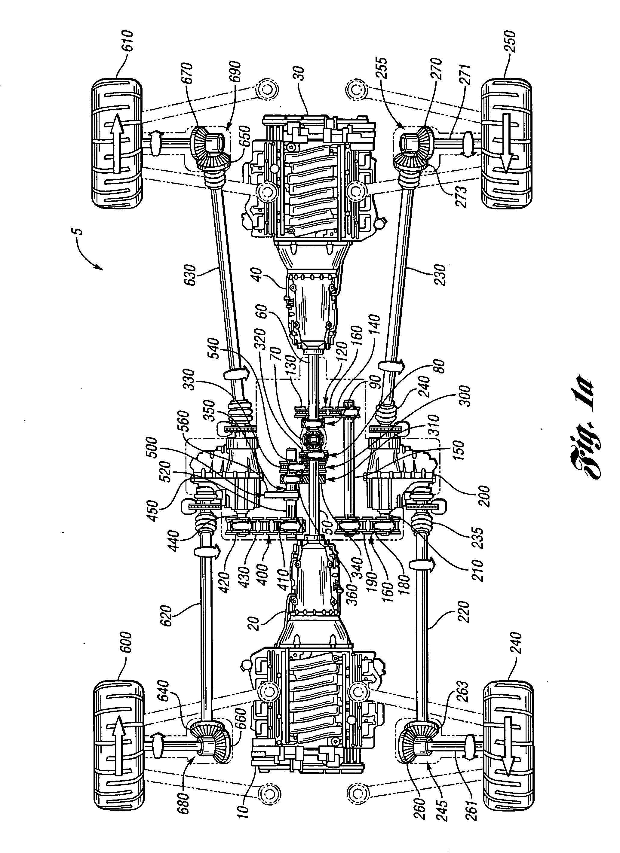
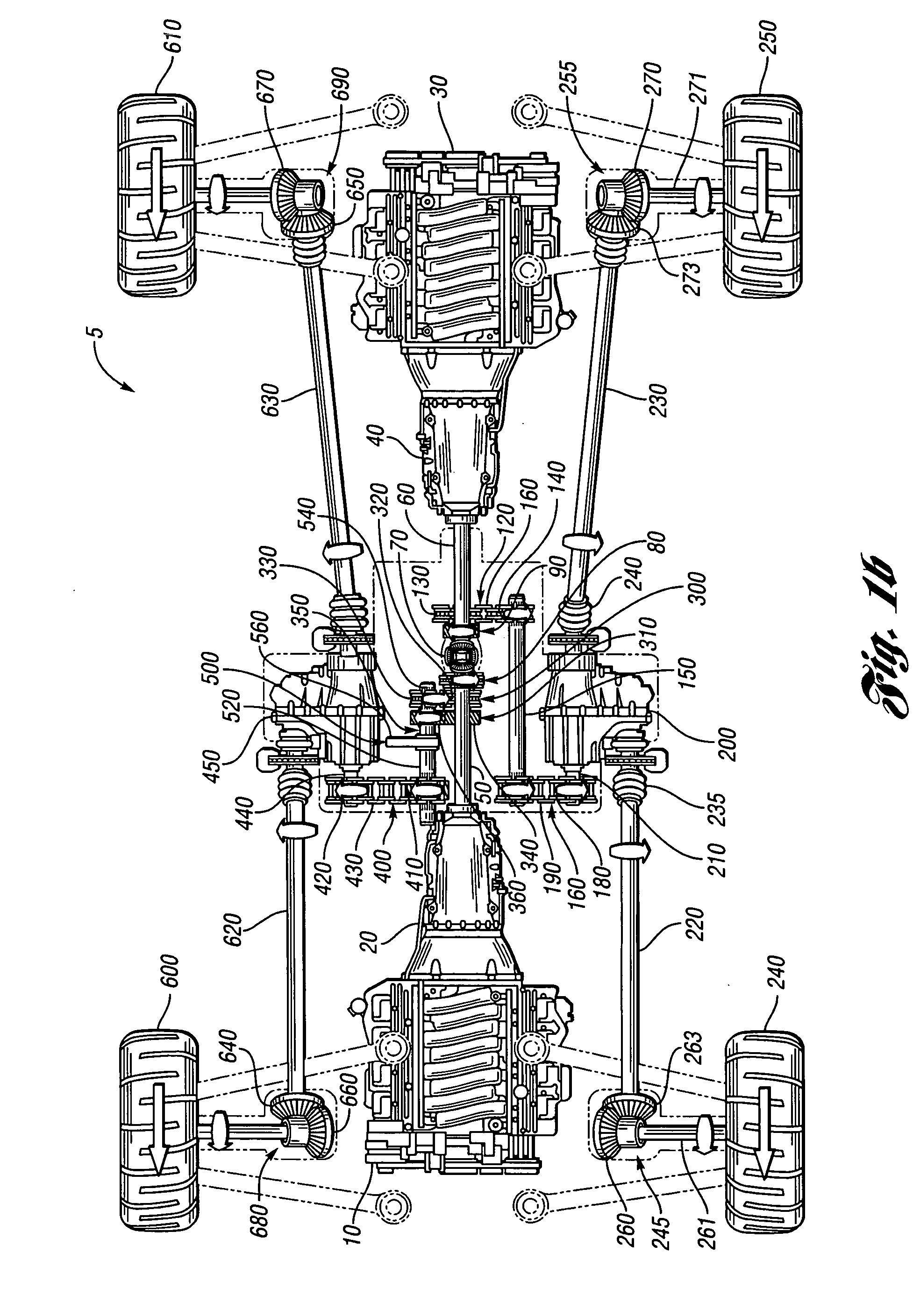
[0026] Transfer case 200, as is known in the art, is used to, among other things, transfer a single torque input to two torque outputs while also selectively providing high and low range operating modes. In this exemplary embodiment, transfer case 200 is used to provide high and low range capability and transfer torque from transfer case input shaft 210 to transfer case output / drive shafts 220 and 230. Drive shafts 220 and 230 are positioned parallel to a wheelbase of vehicle 5 and are coupled to driver side front wheel 240 and driver side rear wheel 250 axle assemblies 245 and 255, respectively. Transfer case output / drive shafts 220 and 230 include typical flexible drive coupling arrangements 235 and 240, such as constant velocity joints as are known in the art.

[0027] Front driver side axle assembly 245 includes a 90 degree pinion gear 260 attached to an end of axle shaft 261 and arranged to engage a 90 degree pinion gear 263 attached to an end of transfer case output shaft 220. At...

case 450

[0031] Transfer case 450, similar to transfer case 200, is utilized to provide high and low range capability and transfer torque from input shaft 440 to passenger side wheels 600 and 610 through transfer case output / drive shafts 620 and 630, respectively. Attached to each end of output shafts 620 and 630 are 90 degree pinion gears 640 and 650, respectively. Pinion gears 640, 650 engage 90 degree pinion gears 660, 670 of driver side front and rear axle assemblies 680, 690, respectively to drive passenger side front and rear wheels 600, 610 in the same fashion as driver side axle assemblies 245, 255 drive front and rear wheels 240, 250.

[0032] Primary intermediate shaft 350 further includes a rotation selection mechanism 500 and splines 520 and 540 positioned relative to gears 410 and 330, 360, respectively. Rotation selection mechanism 500 is envisioned to be any device that can selectively translate shaft 350 in an axial direction and in this exemplary embodiment is a mechanical mech...


PUM


Abstract

A split solid axle arrangement for a vehicle is provided that is arranged to impart a downward force on a wheel of the vehicle. The axle arrangement includes an axle member coupled to a wheel hub at one end and an axle gear member at another end. A drive shaft is attached at one end to a torque transfer mechanism and at another end to a shaft gear member. The drive shaft is orientated perpendicular to the axle member and the shaft gear member is arranged to engage the axle gear member so as to transfer torque from the torque transfer mechanism to the axle member and drive the wheel hub. The drive shaft is arranged to rotate in a direction so as to provide a downward force on the wheel through a transfer of torque from the torque transfer mechanism to the wheel hub.

Description

FIELD OF INVENTION [0001] The present invention relates generally to axle arrangements, and, more particularly, to a split solid axle arrangement for a vehicle BACKGROUND OF INVENTION [0002] The sport utility market today includes, among other things, four wheel drive vehicles that are capable of both on-road and off-road navigation. Generally, for off-road driving or utility work-site applications, the more maneuverable a vehicle is, the more capable the vehicle is in handling various types of terrain or obstacles that may be encountered. Features such as ground clearance and suspension travel play a role in the capability of a vehicle for handling off-road work-site terrain. [0003] Often, in off-road maneuvering such as on trails or at a construction site, obstacles are encountered that require a tight turning radius to be able to maneuver around or avoid the obstacle. Sport utility and construction vehicles have improved their turning radius' over the years, but there is still ro...

Claims


Application Information

Patent Timeline
IPC IPC(8): B60K17/34
CPCB60K5/02B60K5/08B60K17/08B60K17/22B60K17/346B62D7/142B62D7/1509B62D11/006B62D11/04B62D11/08B60K17/358
Inventor LIM, STEPHEN T.QUIGLEY, DOUGLAS J.SMYCZYNSKI, ROBERT
Owner CHRYSLER MOTORS CORP
Learn More