Flexible organic laser printer

a laser printer and flexible technology, applied in printing and other directions, can solve the problems of limiting output resolution, affecting the efficiency of printing,

Inactive Publication Date: 2007-01-18
EASTMAN KODAK CO
View PDF13 Cites 105 Cited by
  • Summary
  • Abstract
  • Description
  • Claims
  • Application Information

AI Technical Summary

Problems solved by technology

The most expensive part of the printer described above is the write laser and associated optics, which need to be precision ground and extremely accurate.
This is generally the limiting factor in output resolution.
While LED arrays are somewhat simpler in design and do not need the rotating mirror, the arrays are expensive to assemble and difficult to align with the photoconductor to achiev...

Method used


Image

  • Flexible organic laser printer
  • Flexible organic laser printer
  • Flexible organic laser printer

Examples


Embodiment Construction

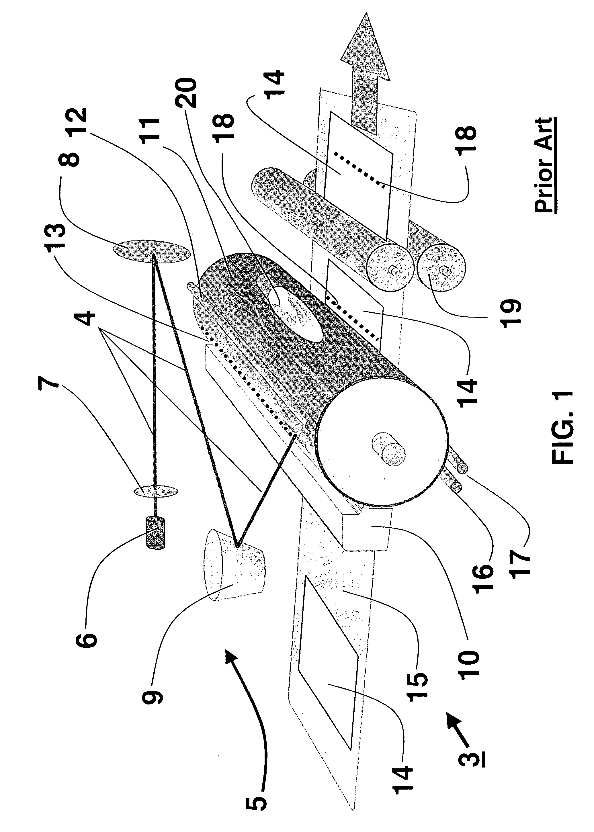
[0050] In a typical prior art electro-photographic printer using the laser printer the most expensive parts are the write laser and its associated optics. This is also generally the limiting factor in output resolution. This is also true in the case where the LED array is used as the printer because of the LED array's complicated assembly and alignment process.

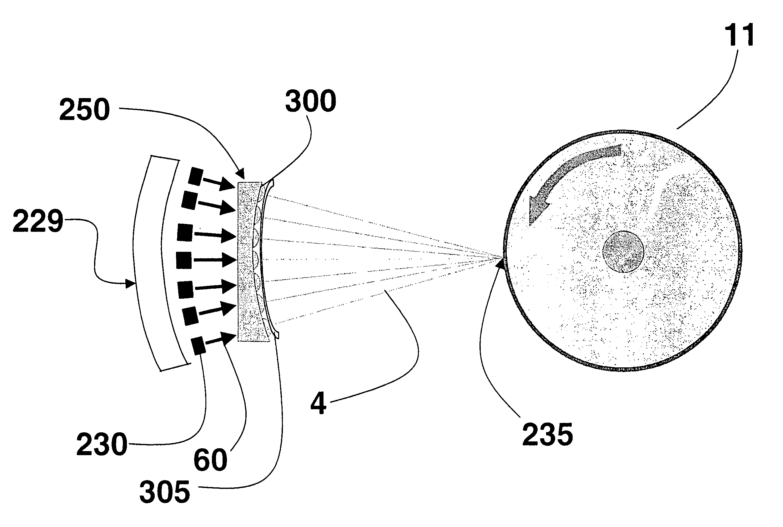
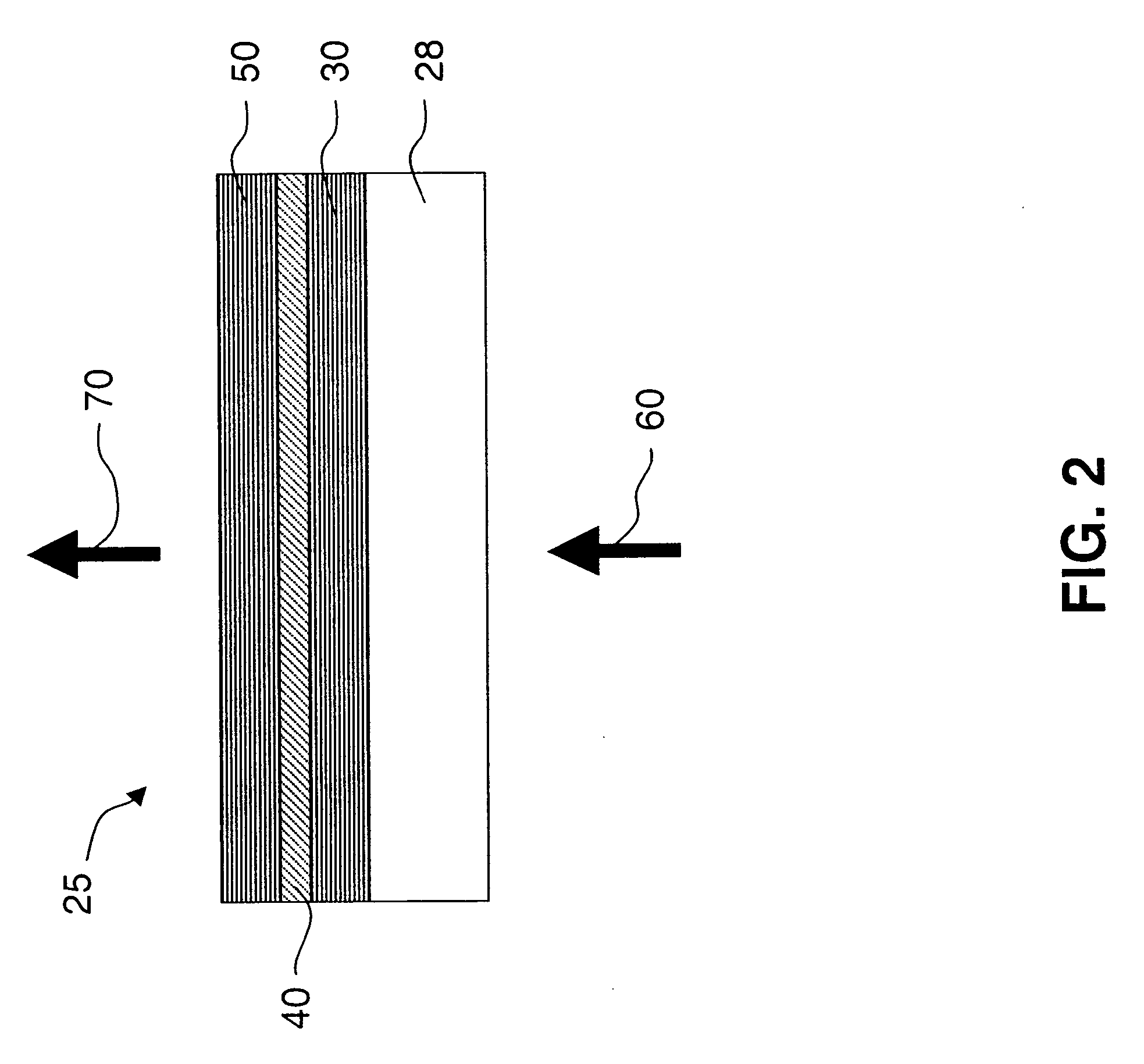
[0051] Instead of using the laser and expensive reflective optics or the LED array and it's complicated assembly it is advantageous to replace these two components with an array of organic lasers. Organic based lasers can be fabricated over large areas and grown on a variety of substrates such as glass, Silica and most importantly flexible plastics. Organic lasers can be available in a broad range of wavelengths allowing optimization with photoconductive material. Print heads made from organic laser arrays will be cheaper to produce with faster output times and higher resolution.

[0052] In the present invention, the terminolo...


PUM


Abstract

A printing device and method for printing. The printing device includes photoconductor for receiving a charge, a plurality of organic vertical cavity surface emitting lasers for producing a charged image pattern on said photoconductor; a toner application mechanism for applying a toner onto said photoconductor for creating a toner image pattern in accordance with said charged image pattern; and a transfer mechanism for transferring said toner image pattern onto a media.

Description

FIELD OF THE INVENTION [0001] The invention relates generally to the field of Vertical Cavity Surface Emitting Lasers (VCSELs) or microcavity lasers, and in particular to organic microcavity lasers or organic VCSELS. More specifically, the invention relates to the various flexible arrays of organic laser cavities used as printing engines. BACKGROUND OF THE INVENTION [0002] Laser printers rely on the same technology used first in photocopying machines. This process is known as electro photography and was invented in 1938 and developed by Xerox and Eastman Kodak in the later 1980s. Prior art laser printer 3 rely on a laser beam 4 and scanner assembly 5 to form a latent image on a photo-conductor 11, wrapped around a drum, bit by bit. The scanning process, as illustrated in FIG. 1, is similar to electron beam scanning used in CRT. The laser 6 produces the beam 4 modulated by electrical signals from the printer's controller (not shown) is directed through a collimator lens 7 and mirror ...

Claims


Application Information

Patent Timeline
IPC IPC(8): B41J2/45
CPCB41J2/45
Inventor HUDSON, NICOLAS H.WIEN, RICHARD W.PATTON, DAVID L.KAHEN, KEITH B.STEPHANY, THOMAS M.CHASE, JAMES G.
Owner EASTMAN KODAK CO
Why Eureka
Try Eureka