
Device for treating food wastes

Inactive Publication Date: 2006-08-03
KIM EE
View PDF3 Cites 21 Cited by
  • Summary
  • Abstract
  • Description
  • Claims
  • Application Information

AI Technical Summary

Benefits of technology

[0008] Accordingly, it is an object of the present invention to provide a device for treating food wastes capable of overcoming the problems encountered in the conventional art wherein a drainage net is no blocked by food remnants, and it is possible to easily remove hard foreign substances without disassembling a food waste treating device even when hard foreign substances are fed.
[0009] It is another object of the present invention to provide a device for treating food wastes capable of discharging the ground food wastes in time and accurately separating food wastes and leachate for thereby minimizing water pollution and significantly decreasing food wastes.
[0010] It is further another object of the present invention to provide a device for treating food wastes capable of preventing the grinding, dehydration and remnant discharging functions from getting worse, and water is not leaked in a direction of a deceleration gear.
[0011] It is still further another object of the present invention to provide a device for treating food wastes according to the present invention in which a food waste box can be easily attached to or detached from a grinding and dehydrating unit, with the food waste box being installed at one side of the grinding and dehydrating unit designed to grind and dehydrate food wastes.
[0012] It is still further another object of the present invention to provide a device for treating food wastes in which a user can known a disposal time of food wastes using the weight of food wastes accumulated in a food waste box without checking the amount of food wastes stored in the food waste box.
[0018] There is further provided a feeding screw which is installed in the interior of the drainage net of the inner casing and includes a spiral wing which is formed at an outer circumferential portion and contacts with the drainage net of the inner casing for thereby guiding the fed food wastes in a downward direction of the inner casing.

Problems solved by technology

Therefore, if flexible and smooth food wastes are fed, the remnants are not well moved and discharged.
In the conventional, it is impossible to know a discharge time of the food wastes because a user cannot check the amount of the food wastes.

Method used


Image

  • Device for treating food wastes
  • Device for treating food wastes
  • Device for treating food wastes

Examples


Embodiment Construction

[0046] The construction and operation of a device for treating food wastes according to the present invention will be described with reference to the accompanying drawings.

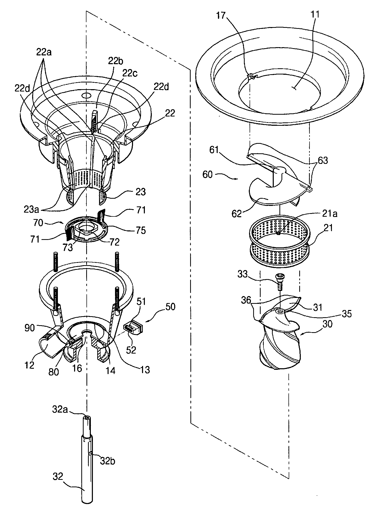
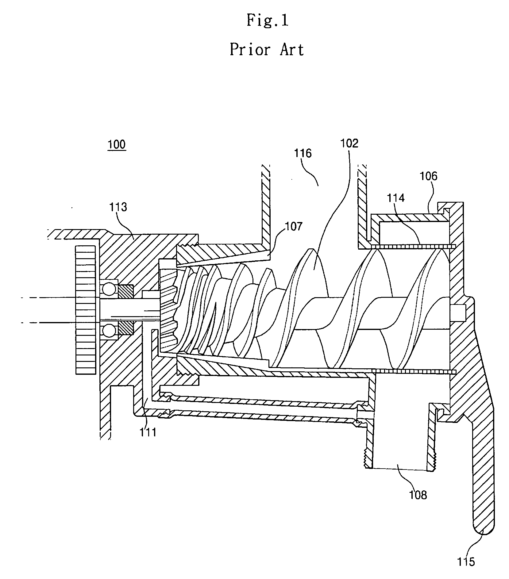
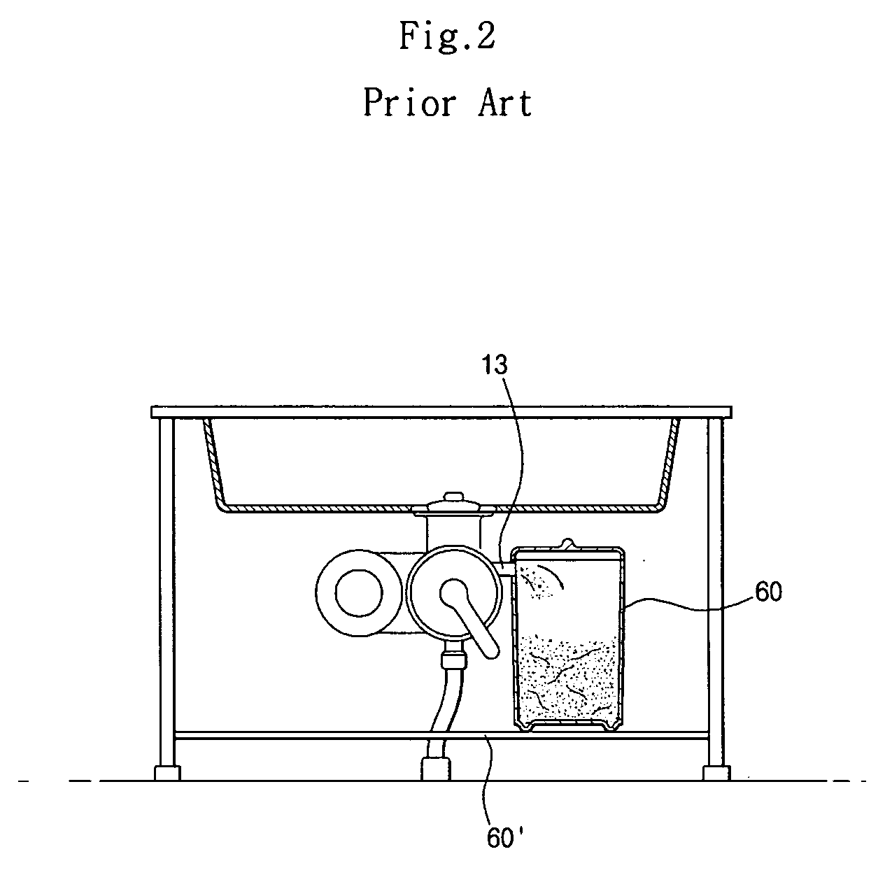
[0047]FIG. 1 is a cross sectional view illustrating a conventional device for treating food wastes; FIG. 2 is a view of a state of use of a conventional device for treating food wastes; FIG. 3 is a partial cut-away and exploded view illustrating a device for treating food wastes according to the present invention; FIG. 4 is a cross sectional view illustrating a device for treating food wastes according to the present invention; FIG. 5A is a plane view illustrating a feeding screw of a device for treating food wastes according to the present invention; FIG. 5B is a side view illustrating a feeding screw of a device for treating food wastes according to the present invention; FIG. 6 is a perspective view illustrating a rotation plate of a device for treating food wastes; FIG. 7 is a perspective view illustrating ke...


PUM


Abstract

The device for treating food wastes is attached to a lower side of a drainage port of a kitchen sink for thereby dehydrating food wastes, grinding the same into small pieces, so that it is possible to significantly decrease the amount of food wastes. The device for treating food wastes comprises a housing which includes a feeding port formed at an upper side of the same for feeding food wastes, a drainage port formed at one side of a lower surface of the same for discharging leachate separated from the fed food wastes, and a discharge hole formed at the other side of the lower surface of the same for discharging dehydrated remnants among the food wastes; an inner casing which is installed at a certain distance from an inner wall of the housing and includes a drainage net installed at an upper side for discharging water fed together with the food wastes, a drum which is installed at a center of the same and has a plurality of wall surface blades at an inner circumferential surface, and a dehydration net installed at a lower side of the same for discharging leachate; a grinding screw which is vertically installed at an inner side of the inner casing and includes a plurality of screw blades installed at an outer circumferential portion and contacting with a wall surface blade of the drum, and the dehydration net.

Description

BACKGROUND OF THE INVENTION [0001] 1. Field of the Invention [0002] The present invention relates to a device for treating food wastes capable of significantly decreasing food wastes in such a manner that a device for treating food wastes is installed at a lower side of a drainage port of a kitchen sink for thereby dehydrating and grinding food wastes. [0003] 2. Description of the Background Art [0004] Generally, a food waste treating device has a body formed of a feeding part for feeding food wastes, a discharge part for discharging food wastes, and a screw for grinding food wastes. [0005] The Korean patent laid-open No. 240229 invented and filed by the applicant of the present invention discloses a conventional device for treating food wastes. As shown in FIG. 1, in the above conventional device 100 for treating food wastes, a grinding screw 102 is engaged at a drum body 106 having a cutting blade 107 and a drainage port 108. The food wastes are dehydrated in such a manner that th...

Claims


Application Information

Patent Timeline
IPC IPC(8): B02C19/22
CPCB02C19/22E03C1/2665
Inventor KIM
Owner KIM EE
Learn More