

Projector system
a projector and projector technology, applied in the field of projector systems, can solve the problems of long time, poor operability of the approach, and user-friendly system, and achieve the effect of improving the display quality, and improving the display quality
- Summary
- Abstract
- Description
- Claims
- Application Information
AI Technical Summary
Benefits of technology
Problems solved by technology
Method used
Image

Examples
embodiment 1
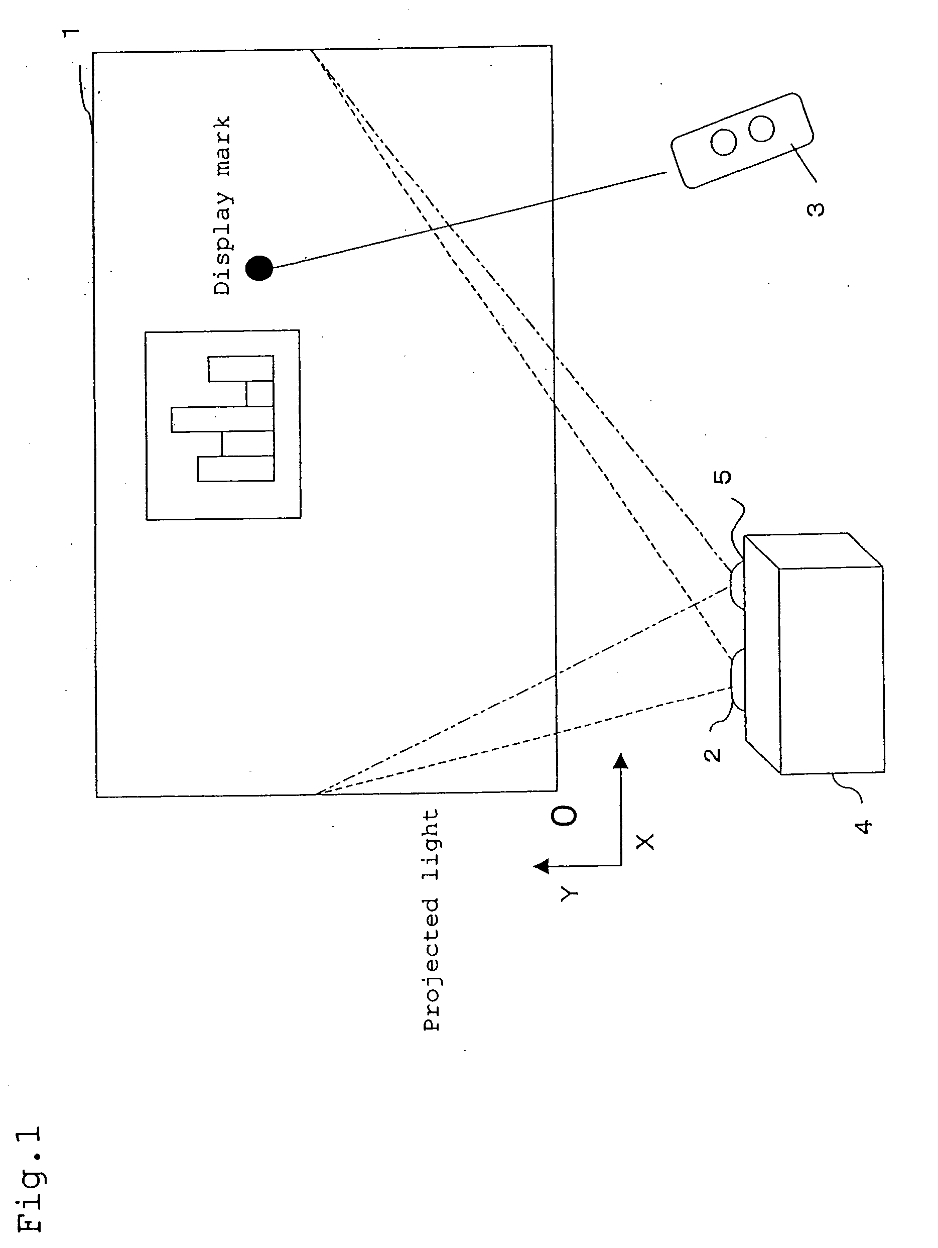
[0216]FIG. 1 shows a schematic configuration of a projector system according to Embodiment 1 of the present invention.
[0217] In the projector system shown in FIG. 1, a projector unit 4 is provided with a projection lens 2 and a detection lens 5. A screen 1 serving as an example of the projection target of the present invention is arranged in a manner opposing to the projection lens 2 and the detection lens 5. A laser pointer 3 serving as an example of the pointing section of the present invention is arranged such as to project light toward the screen 1 when switched ON. The detection lens 5 is arranged in a manner adjusted such that the entire image projected on the screen 1 can be acquired.
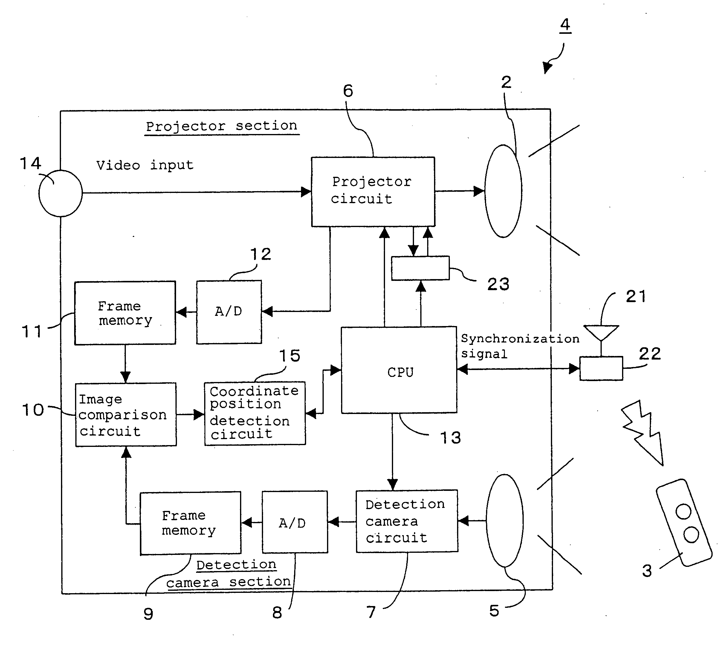
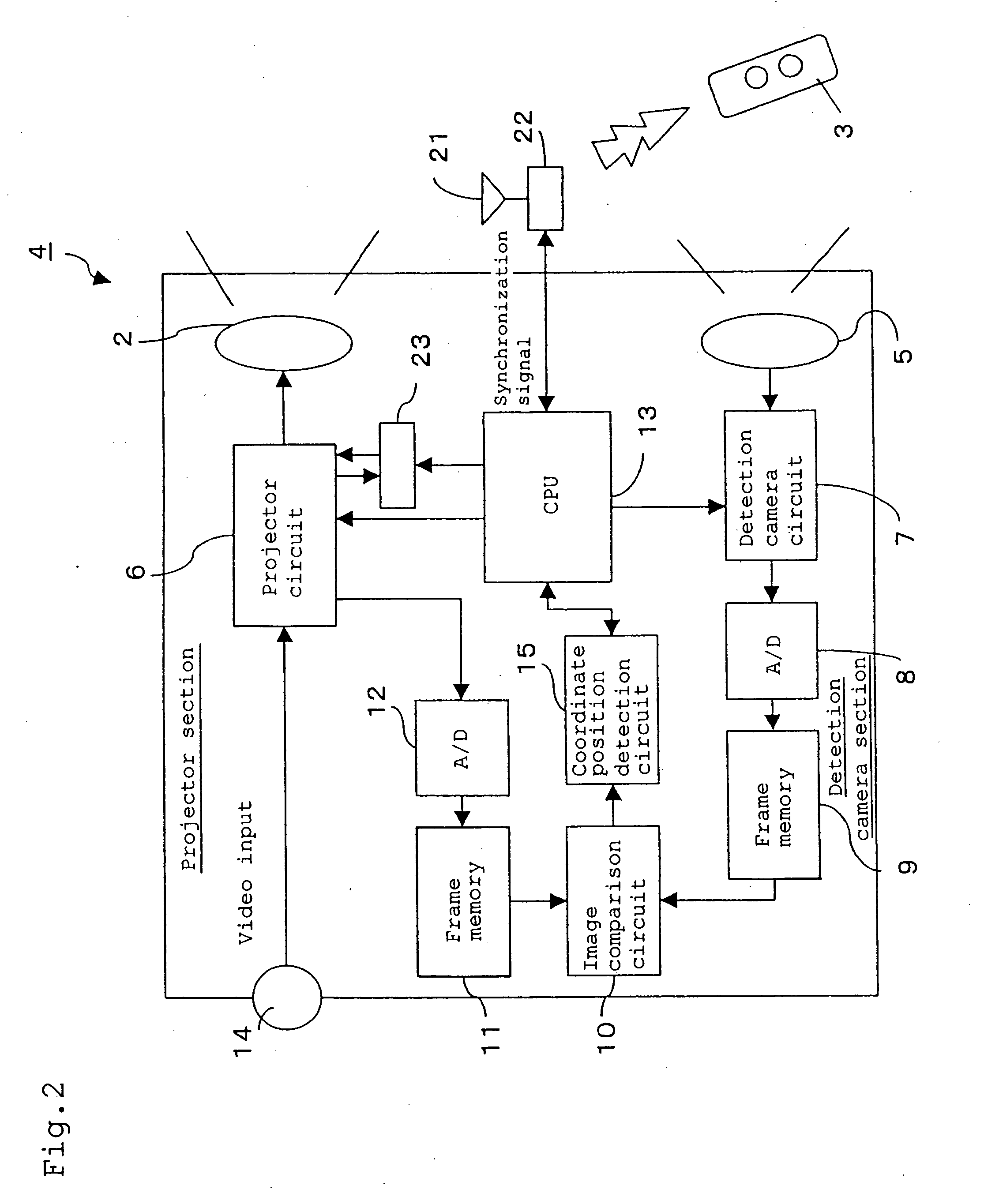
[0218]FIG. 2 is a block diagram showing an internal configuration of the projector unit 4.
[0219] In the projector unit 4 shown in FIG. 2, a projector circuit 6 connected to a video input terminal 14 is arranged behind the projection lens 2. The projector circuit 6 includes a liquid crystal dis...
embodiment 2
[0239]FIG. 6 shows a schematic configuration diagram of a projector system according to Embodiment 2. The structure of the projector system according of Embodiment 2 is similar to that of the projector system of Embodiment 1, and hence its description is omitted. In the projector system of Embodiment 2, as shown in FIG. 6, a GUI (Graphic User Interface) display area 24 serving as an example of the operation display area of the present invention is displayed on the screen 1, in a manner added to the video signal inputted through the video input terminal 14. In the GUI display area 24 of the example shown in FIG. 6, a forward page feed mark, a backward page feed mark, and a list display mark are displayed.
[0240]FIG. 7 is a block diagram showing the configuration that realizes display on the screen 1. In the block diagram of FIG. 7, like components to those of the projector system of Embodiment 1 are designated by like reference numerals, and hence their description is omitted.
[0241]...
embodiment 3
[0252]FIG. 8 is a block diagram showing the configuration of a projector system according to Embodiment 3 of the present invention.
[0253] In the projector system shown in FIG. 8, like components to those of the projector system of Embodiments 1 and 2 are designated by like reference numerals, and hence their description is omitted. The projector system of the present embodiment has a luminance filter circuit 27 on the output side of the detection camera circuit 7.
[0254] In the present embodiment, the video input terminal 14, the memory 26, the projector circuit 6, and the projection lens 2 correspond to an example of the first projection section of the present invention. The CPU 13 and the coordinate position detection circuit 15 correspond to an example of the pointed position detecting section in the projector system of the first aspect of the present invention. The detection lens 5, the detection camera circuit 7, and the luminance filter circuit 27 correspond to an example of ...
PUM
 Abstract
Description
Claims
Application Information