Reagent container and slide reaction and retaining tray, and method of operation

Active Publication Date: 2006-08-03
SAKURA FINETEK U S A
View PDF99 Cites 40 Cited by
  • Summary
  • Abstract
  • Description
  • Claims
  • Application Information

AI Technical Summary

Benefits of technology

[0014] The size of the space between the tray platen and slide can be configured to create fluid flow properties as desired. In an embodiment, the reaction chamber width (i.e. distance between platen and slide) is thin enough so as to promote capillary action induced fluid flow from one end to the other. Preferably the fluid flow is from the reagent recess end towards the opposite end. In this way, reagents flow via capillary action from the recess towards the opposite end of the reaction chamber. Moreover, secondary or other reagents introduced from above on

Problems solved by technology

There are various disadvantages of known systems.
For example, manually pouring into, or draining, reagent vats is time consuming and requires pouring accuracy, thereby decreasing the overall efficiency of the tissue processing system.
Another disadvantage is that manually pouring and draining reagents can be sloppy, requiring clean-up of spills and consequential instrument down-time.
A further disadvantage is that selecting the correct re

Method used


Image

  • Reagent container and slide reaction and retaining tray, and method of operation
  • Reagent container and slide reaction and retaining tray, and method of operation
  • Reagent container and slide reaction and retaining tray, and method of operation

Examples


Embodiment Construction

[0039] In the following paragraphs, the present invention will be described in detail by way of example with reference to the figures. Throughout this description, the preferred embodiment and examples shown should be considered as exemplars, rather than as limitations on the present invention. As used herein, the “present invention” refers to any one of the embodiments of the invention described herein, and any equivalents. Furthermore, reference to various feature(s) of the “present invention” throughout this document does not mean that all claimed embodiments or methods must include the referenced feature(s).

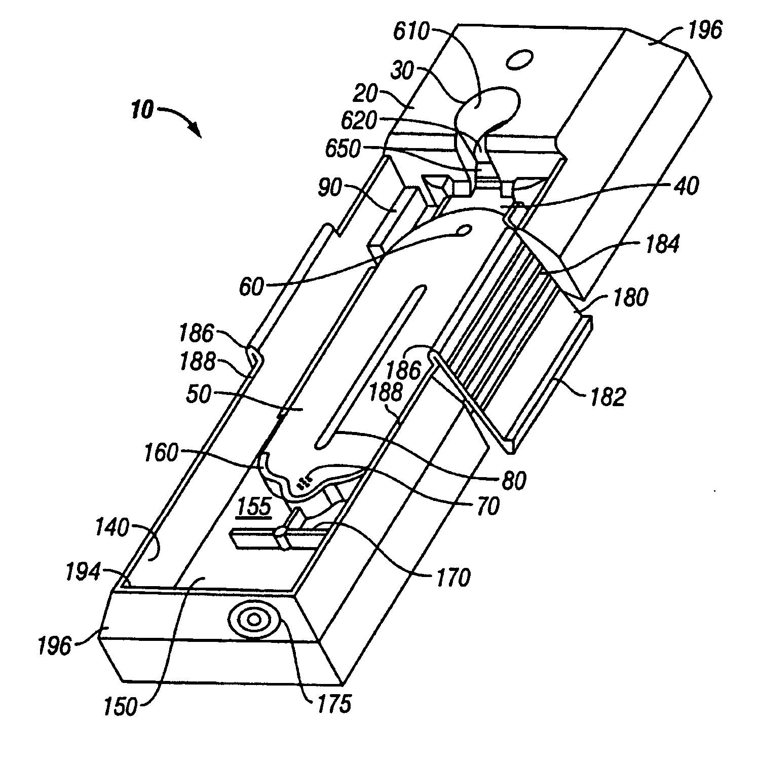
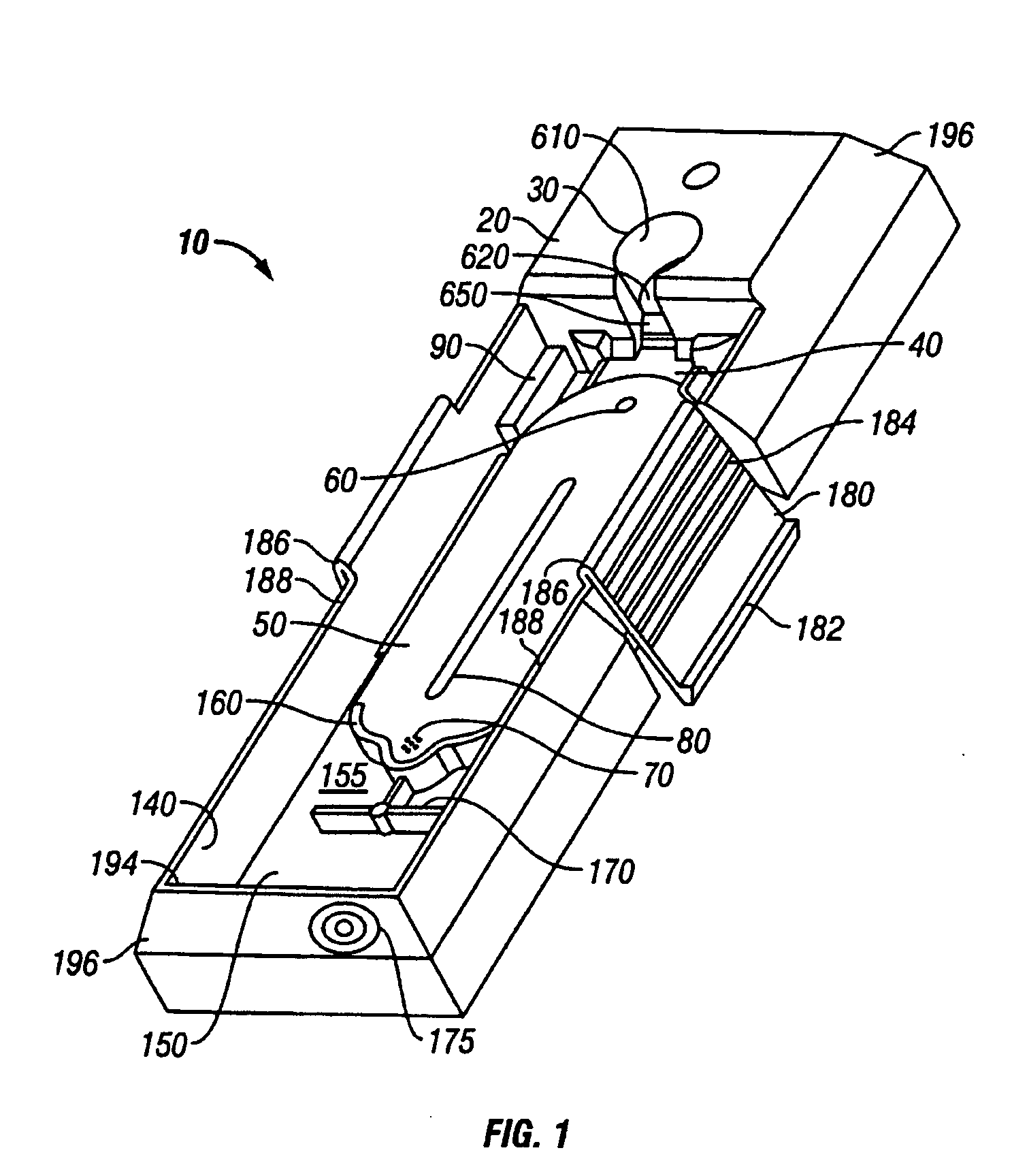
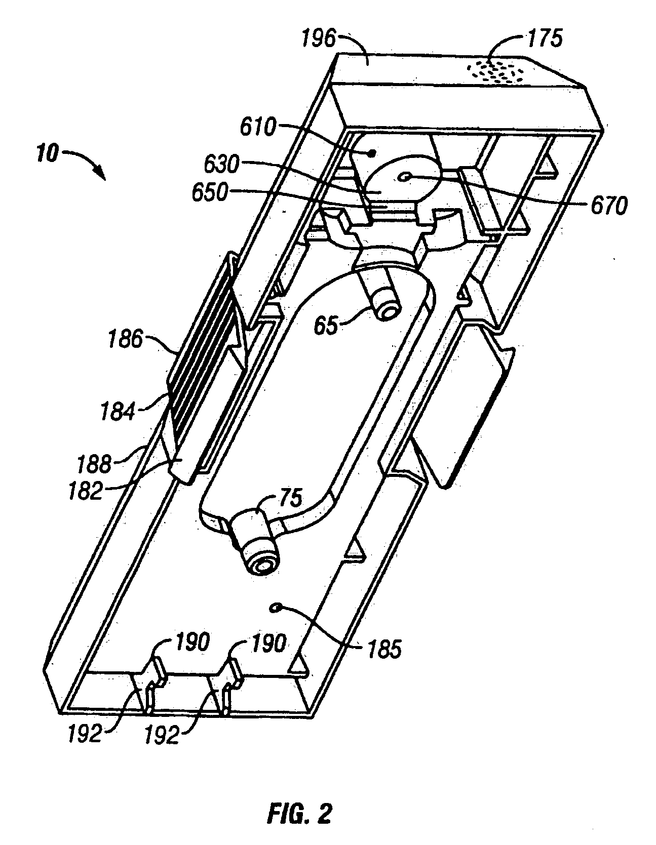
[0040] A sample or slide retaining tray 10 in accordance with the principles of the present invention is illustrated in the figures and described in the following paragraphs. As used herein the terms sample retaining tray and slide retaining tray are used interchangeably for a retaining tray 10 that can retain a sample and / or slide. In the illustrated embodiment, sample reta...


PUM

PropertyMeasurementUnit
Flow rateaaaaaaaaaa
Levelaaaaaaaaaa
Humidityaaaaaaaaaa

Abstract

A sample, or slide, retaining tray includes a reagent reservoir, or recess, and a reaction chamber. A slide, or other sample container, can be positioned on the sample retaining tray as desired, with a tissue specimen face down, between a platen on the tray and the slide. A reagent from the reservoir is rendered flowable, such as by heating, and flows from the reservoir into the reaction chamber. Optionally, reagents or other fluids can be provided from above, by dripping onto a drip surface of the sample retaining tray, or below via an inlet port in the platen.

Description

[0001] Priority is claimed to U.S. Provisional Pat. App. Ser. No. 60 / 652,170, entitled “Reagent Container and Slide Reaction And Retaining Tray, And Method of Operation, filed Feb. 11, 2005, the contents of each of which are incorporated in their entireties herein by reference. This application also is a continuation-in-part of co-pending U.S. patent application Ser. No. 10 / 639,021, filed on Aug. 11, 2003, and entitled “Fluid Dispensing Apparatus”, which is incorporated herein by reference in its entirety.FIELD OF THE INVENTION [0002] The present invention is directed generally to a tissue sample processing system and, in particular, to a sample retaining tray used in such a system. BACKGROUND OF THE INVENTION [0003] Tissue processors can be operated with varying levels of automation to process human or animal tissue specimens for histology or pathology uses. Various types of chemical reagents can be used at various stages of tissue processing and various systems have been developed...

Claims


Application Information

Patent Timeline
IPC IPC(8): B01L3/00
CPCB01L3/502715B01L9/52B01L2300/041B01L2300/0822B01L2300/0877B01L2400/0406Y10T436/112499B01L2400/0487B01L2400/0677G01N1/312G01N35/00029G01N2035/00138Y10T436/11B01L2400/0457
Inventor STEAD, RONALD H.BUI, XUAN S.
Owner SAKURA FINETEK U S A
Why Eureka
Try Eureka