Ultrasonographic method and ultrasonographic device

a technology of ultrasonography and ultrasonography, applied in the field of ultrasonography, can solve the problem of not considering reducing the time side lobe, and achieve the effect of time side lob

Inactive Publication Date: 2006-08-03
HITACHI MEDICAL CORP
View PDF0 Cites 30 Cited by
  • Summary
  • Abstract
  • Description
  • Claims
  • Application Information

AI Technical Summary

Benefits of technology

[0083] A principle of obtaining the advantages of this embodiment will be described with reference to FIG. 8 again. When a subject has a body motion (such as a movement), the encoding reception signals corresponding to two modulation codes A and B in an encoding set are demodulated to obtain demodulation signals. Synthesizing the obtained demodulation signals results in a demodulation synthesis signal P1 (first synthesis signal). The time side lobe occurring in the demodulation synthesis signal P1 is due to the body motion resulting from forward movement of a subject. Next, encoding reception signals corresponding to two modulation codes −B and −A in the opposite encoding set are demodulated to obtain the demodulation signals. Synthesizing the obtained demodulation signals results in a demodulation synthesis signal P2 (second synthesis signal). The time side lobe occurring in the demodulation synthesis signal P2 is an equivalent signal to the one due to the body motion resulting from relatively reverse movement of a subject with reference to that of the time side lobe of the demodulation synthesis signal P1.

Problems solved by technology

However, while the time side lobe may occur due to nonlinearlity of a medium within a subject and / or a body motion (such as a change in position or form with time), the conventional technology does not consider reducing the time side lobe due to a body motion of a subject.

Method used


Image

  • Ultrasonographic method and ultrasonographic device
  • Ultrasonographic method and ultrasonographic device
  • Ultrasonographic method and ultrasonographic device

Examples


first embodiment

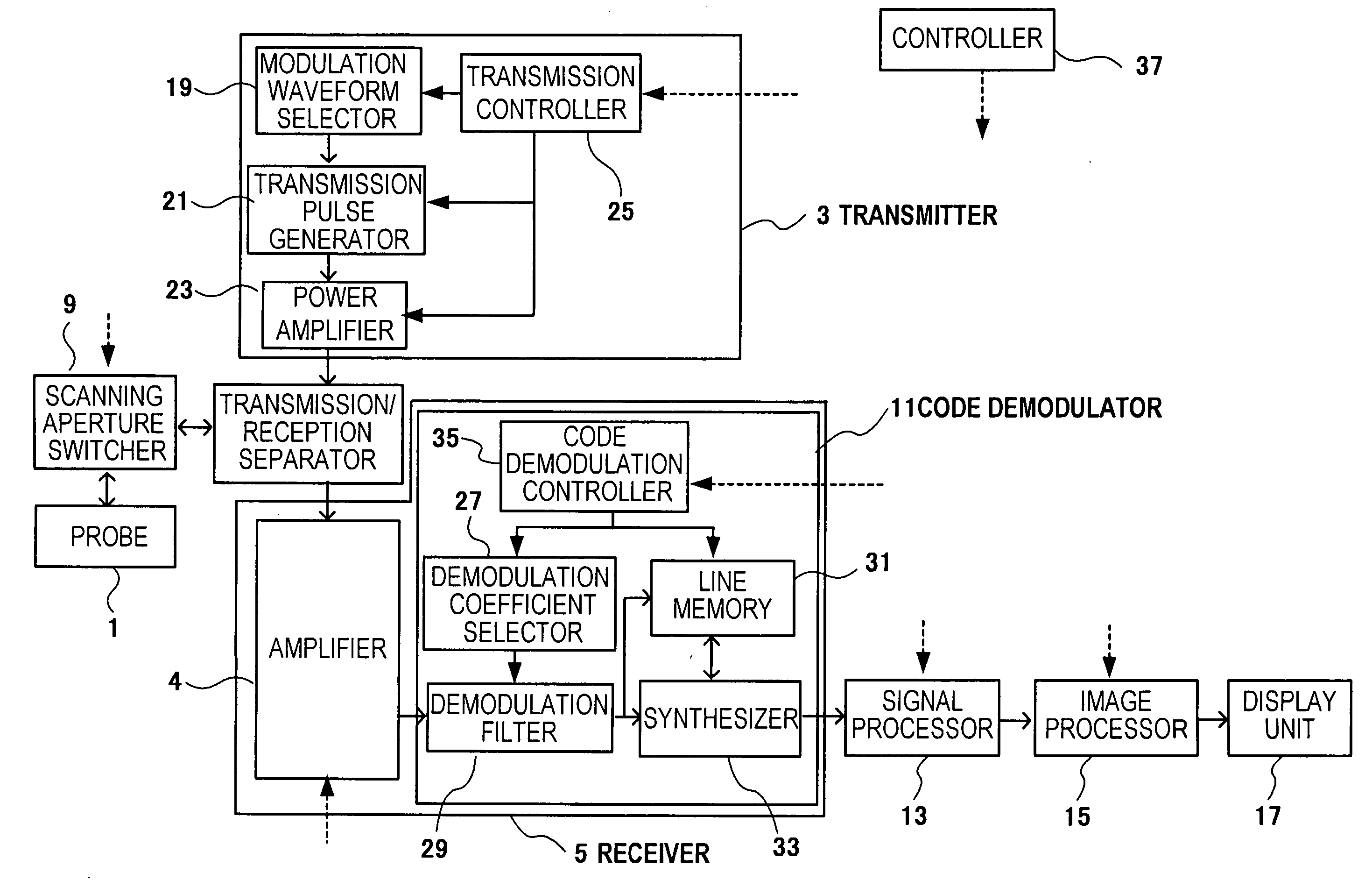
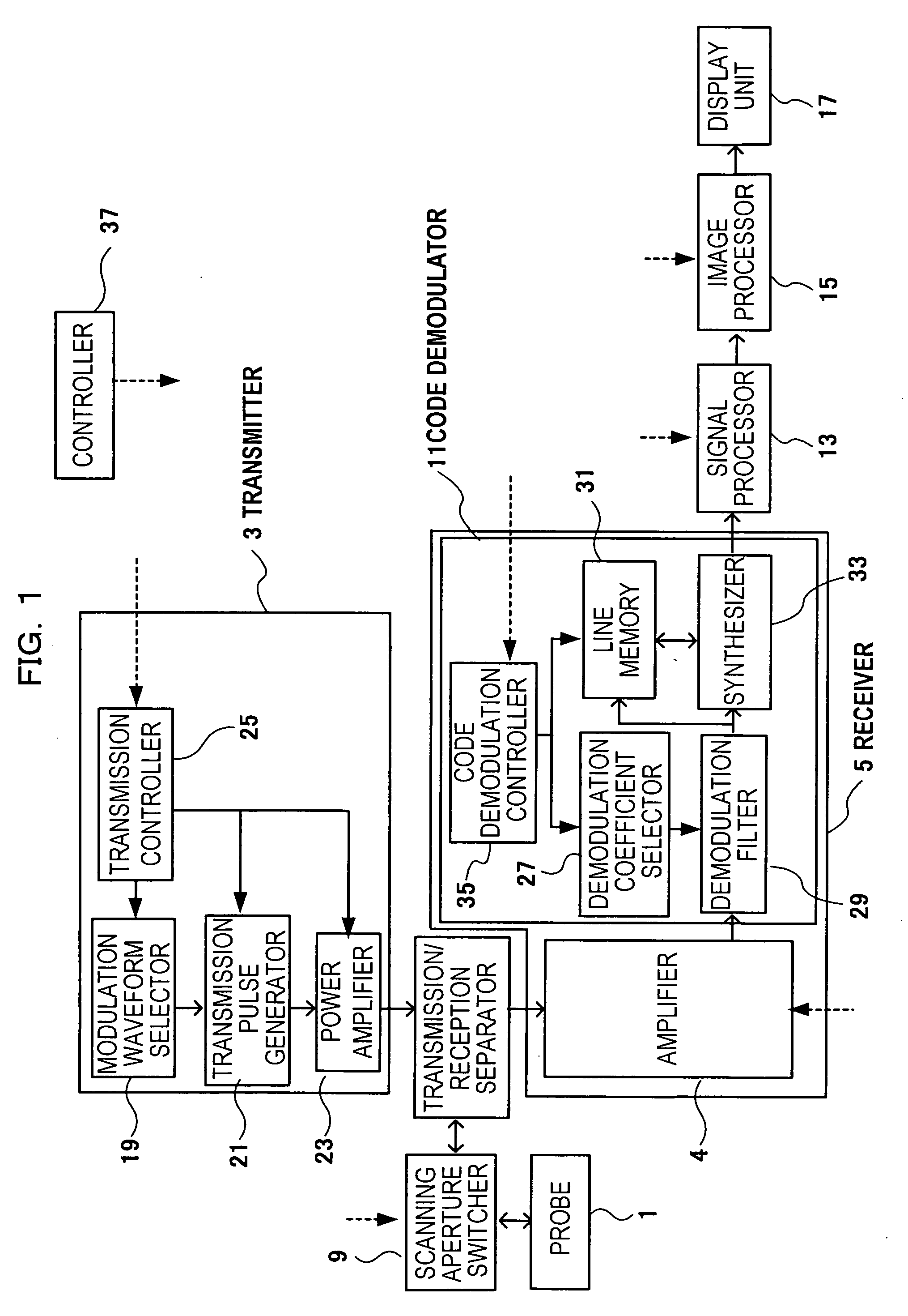
[0037] A first embodiment of an ultrasonographic device applying the present invention will be described. FIG. 1 is a block diagram showing a construction of an ultrasonographic device of this embodiment. The ultrasonographic device includes a probe 1, a transmitter 3 and a receiver 5. The probe 1 transmits / receives an ultrasonic wave. The transmitter 3 outputs a drive signal for the probe 1. The receiver 5 is for a reflection echo signal (called reception signal, hereinafter) output from the probe 1. Furthermore, a transmit / receive separator 7 is provided therein for transmitting a drive signal output from the transmitter 3 and transmitting a reception signal output from the probe 1 to the receiver 5.

[0038] A scan aperture switcher 9 is provided between the probe 1 and the transmit / receive separator 7. The scan aperture switcher 9 selects a transducer having the aperture of the probe 1 from multiple transducers of the probe 1. Furthermore, a signal processor 13, an image processor...

example 1-1

[0070]FIG. 7 shows simulation results and the fact that the time side lobe is reduced even when an amplification distortion occurs in a reception signal due to a body motion of a subject, for example. FIG. 7 shows graphs having waveforms of an encoding reception signal, demodulation signal, first and second synthesis signals and third synthesis signal in order from the left column. The first and second synthesis signals are referred by the first and second demodulation synthesis signals, and the third synthesis signal is referred by the synthesis signal. The vertical axis of the graphs indicates strength of signals. The horizontal axis of the graphs indicates time. FIG. 7 shows a case of the first encoding transmission / reception based on the modulation code A, a case of the second encoding transmission / reception based on the modulation code B, a case of the third encoding transmission / reception based on the modulation code −B and a case of the fourth encoding transmission / reception ...

example 1-2

[0074]FIG. 8 shows similar graphs to those in FIG. 7 but shows a case that a phase distortion due to a body motion occurs in an encoding reception signal instead of an amplitude distortion. As shown in FIG. 8, the time side lobe due to a body motion occurs in each of the demodulation synthesis signals P1 and P2. Thus, in this example, as shown in the rightmost column in FIG. 8, further synthesizing the demodulation synthesis signal P1 and demodulation synthesis signal P2 results in a synthesis signal having a reduced time side lobe.

[0075] A case that a frequency distortion occurs in an encoding reception signal may be handled in the same manner as that of the case that an amplitude distortion occurs in an encoding reception signal (FIG. 8).


PUM


Abstract

An ultrasonographic method includes: a first encoding transmission / reception step for transmitting an ultrasonic beam encoded by an encoding set consisting of a plurality of modulation codes in which at least two are in complementary relationship and demodulating reception signals corresponding to the ultrasonic beam; a step for obtaining a first synthesis signal by synthesizing the demodulation signals demodulated by the first encoding transmission / reception step; a second encoding transmission / reception step for transmitting an ultrasonic beam encoded by a reverse encoding set consisting of a plurality of modulation codes in which the arrangement order of modulation codes of the encoding set is reversed and demodulating the reception signals corresponding to the ultrasonic beam; a step for obtaining a second synthesis signal by synthesizing the demodulated signals demodulated by the second encoding transmission / reception step; a step for obtaining a third synthesis signal by synthesizing the first synthesis signal and the second synthesis signal; and a step for reconstructing the ultrasonograph according to the third synthesis signal.

Description

TECHNICAL FIELD [0001] The present invention relates to an ultrasonographic method with encoding transmissions / receptions and an ultrasonographic device. BACKGROUND ART [0002] An encoding transmission / reception technology is adopted in an ultrasonographic method and ultrasonographic device in order to enhance a resolution of an ultrasonograph. A complementary encoding technology typically such as Golay (Golay, M. J. E. Complementary Series. IRE Trans. Inform. Theory, IT-7, pp. 82-87, April 1961) is known as the encoded exchange technology. According to the technology, an encoding set including two complementary modulation codes (A and B) is available, and a basic wave is modulated by the modulation codes (A and B) in the encoding set and is output to a probe as encoding drive signal so that an encoded ultrasonic beam can be transmitted from the probe to a subject. The two received signals corresponding to the ultrasonic beam are demodulated and synthesized so that the time side lobe...

Claims


Application Information

Patent Timeline
Patent Type & Authority Applications(United States)
IPC IPC(8): A61B8/00G01S7/52G01S15/89
CPCG01S7/52023G01S15/8959G01S15/8961
Inventor ASAFUSA, KATSUNORIKANDA, HIROSHI
Owner HITACHI MEDICAL CORP
Why Eureka
Try Eureka