Apparatus And Method of Lensing An Ultrasonic Beam For An Ultrasonic Flow Meter

an ultrasonic flow meter and ultrasonic technology, applied in the direction of volume/mass flow measurement, measurement devices, instruments, etc., can solve the problems of low signal-to-noise ratio, less accurate detection and measurement of transmitted ultrasonic signals, and negative effects on the signal-to-noise ratio of devices, so as to optimize the signal characteristics of ultrasonic signals and achieve high power transmission of ultrasonic signals. , the effect of accurate sens

Active Publication Date: 2008-05-01
EXPRO METERS
View PDF99 Cites 30 Cited by
  • Summary
  • Abstract
  • Description
  • Claims
  • Application Information

AI Technical Summary

Benefits of technology

[0015]An advantage of the present invention method and apparatus is that a fluid flow having bubbles and/or particles entrained within the fluid flow can more accurately be sensed. Depending upon the specific flow conditions, the lens can be used to colliminate, diverge or converge the ultrasonic signal within the pipe to thereby optimize the signal characteristics of the ultrasonic signal at the receiver. For example, an ultrasonic signal beam that is colliminated within the fluid flow is less susceptible to being completely blocked by the bu

Problems solved by technology

Multiphase fluid flows pose certain issues for flow meters utilizing ultrasonic sensors.
The attenuation of the signal may result in a low signal-to-noise ratio, which in turn can make it more difficult to accurately detect and measure the transmitted ultrasonic signal.
For those ultrasonic flow meters that utilize transmitter/receiver sensor units disposed outside the flow pipe the signal-to-noise ratio of the device can also be negatively affected by undesirable “secondary” signals that are portions of the original signal that have been refracted or refle

Method used


Image

  • Apparatus And Method of Lensing An Ultrasonic Beam For An Ultrasonic Flow Meter
  • Apparatus And Method of Lensing An Ultrasonic Beam For An Ultrasonic Flow Meter
  • Apparatus And Method of Lensing An Ultrasonic Beam For An Ultrasonic Flow Meter

Examples


Embodiment Construction

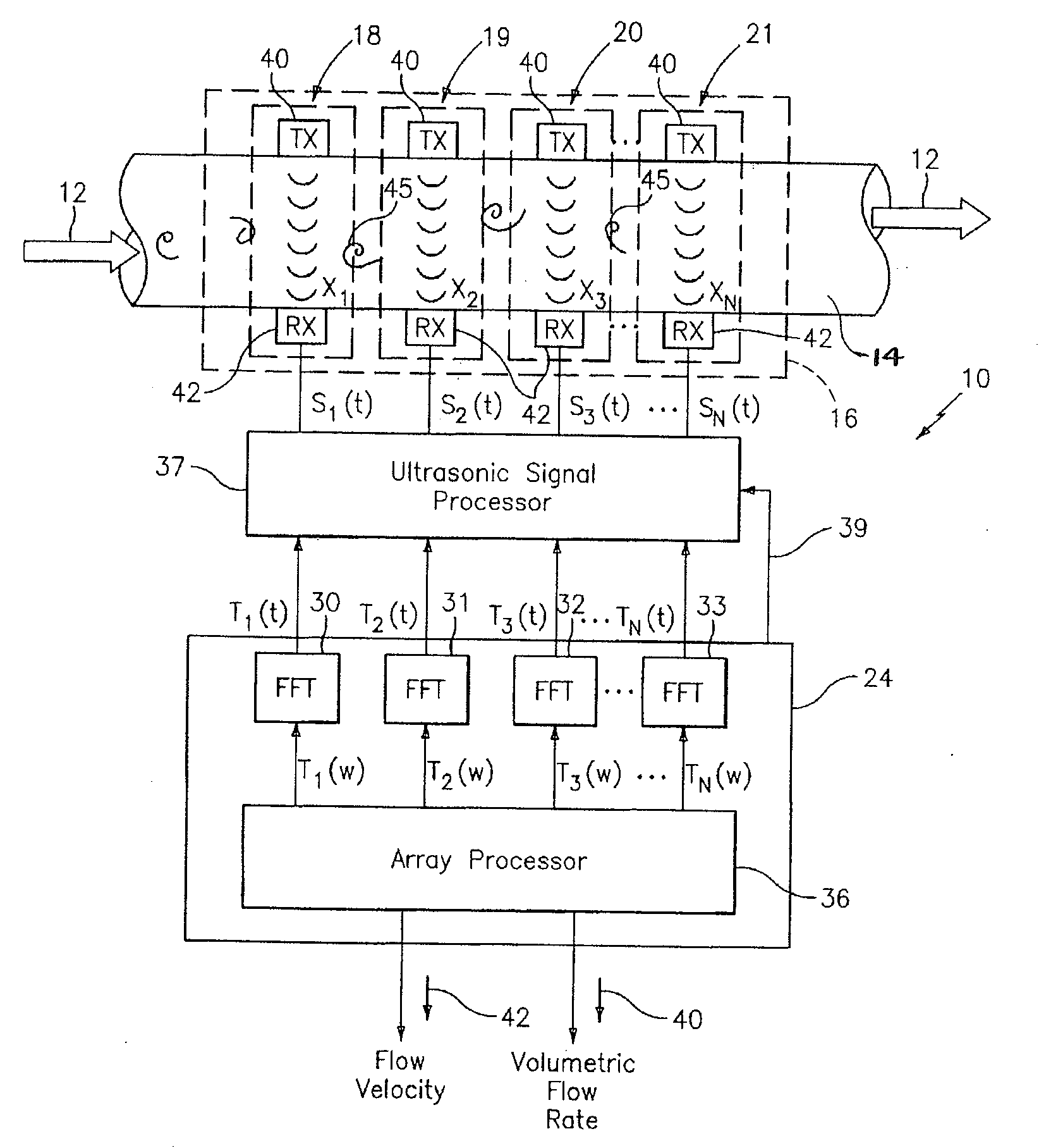
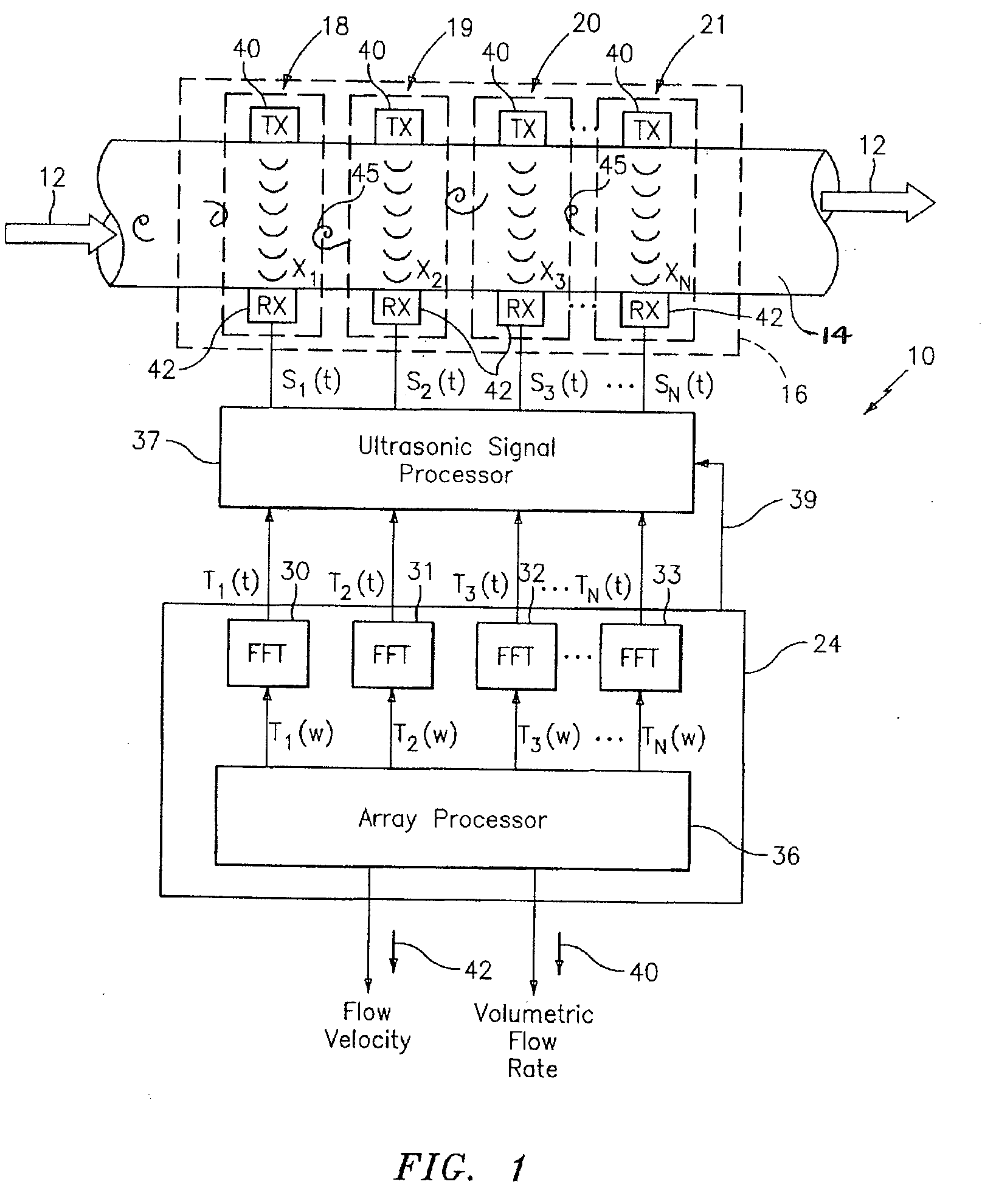
[0030]The invention teaches methods to optimize the signal properties of a transmitted ultrasonic beam passing through a fluid flow having entrained particles or bubbles, the ultrasonic beam being provided by a clamp-on flow ultrasonic flow meter, similar to that described in U.S. patent application Ser. No. 10 / 756,977, filed Jan. 13, 2004, which is incorporated herein by reference.

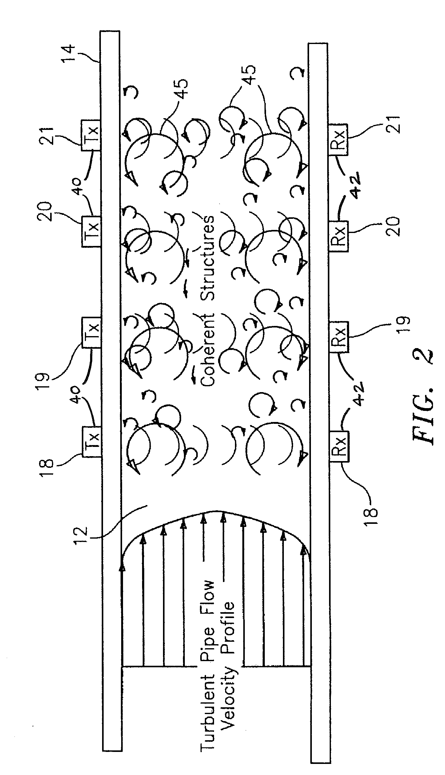
[0031]FIGS. 1 and 2 diagrammatically depict an ultrasonic clamp-on flow meter 10, an example of which is described in U.S. patent application Ser. No. 10 / 756,977. The ultrasonic flow meter 10 includes an array of ultrasonic sensors 16 having a plurality of ultrasonic sensor units 18-21 disposed axially along the length of the pipe 14. Each ultrasonic sensor unit 18-21 comprises a transmitter 40 and a receiver 42. The transmitter 40 provides an ultrasonic signal to the corresponding receiver 42, wherein the ultrasonic signal is orthogonal to the direction of the fluid flow 12. While this embodiment of the ...


PUM


Abstract

A method for sensing flow within a pipe having an internal passage disposed between a first wall portion and a second wall portion is provided, comprising the steps of: 1) providing a flow meter having at least one ultrasonic sensor unit that includes an ultrasonic transmitter attached to the first wall portion and an ultrasonic receiver attached to the second wall portion and aligned to receive ultrasonic signals transmitted from the transmitter; 2) selectively operating the ultrasonic transmitter to transmit a beam of ultrasonic signal, which beam has a focal point such that within the pipe, the beam is either colliminated, divergent or convergent; and 3) receiving the ultrasonic signals within the beam using the ultrasonic receiver. An apparatus operable to perform the aforesaid method is also provided.

Description

[0001]Applicant hereby claims priority benefits under 35 U.S.C. § 119(e) of U.S. Provisional Patent Application No. 60 / 856,244 filed Nov. 1, 2006, the disclosure of which is herein incorporated by reference.CROSS-REFERENCE TO RELATED PATENT APPLICATIONS[0002]The present application relates to U.S. Patent Application No. 60 / 856,243 filed on Nov. 1, 2006, U.S. patent application Ser. No. 10 / 756,977, filed Jan. 13, 2004 and U.S. Provisional Patent Application No. 60 / 833,651, filed Jul. 27, 2006, which are incorporated by reference herein in their entirety.BACKGROUND OF THE INVENTION[0003]1. Technical Field[0004]This invention relates to methods and apparatus for improving the signal-to-noise ratio of ultrasonic sensors utilized for sensing fluid flow within a pipe in general, and to methods and apparatus for lensing an ultrasonic beam or signal to optimize the signal properties of the transmitted ultrasonic beam passing through a fluid flow having entrained particles or bubbles.[0005]2...

Claims


Application Information

Patent Timeline
IPC IPC(8): G01F1/66G01F1/7082
CPCG01F1/666G01F1/74G01F1/7082G01F1/667
Inventor BAILEY, TIMOTHY J.FERNALD, MARKDANG, CHANGJIU
Owner EXPRO METERS
Why Eureka
Try Eureka