Rigid-contact dripless bubbler (RCDB) apparatus for acoustic inspection of a workpiece in arbitrary scanning orientations

a dripless, workpiece technology, applied in the direction of instruments, magnetic properties, analysing solids using sonic/ultrasonic/infrasonic waves, etc., can solve the problems of cab devices that are too large in overall size and footprint, too costly for many applications, and cab size, etc., to achieve reliable ultrasonic coupling, spoil the quality of ultrasonic coupling, and eliminate debris and bubbles attached

Inactive Publication Date: 2007-10-23
FLEMING MARVIN F
View PDF3 Cites 37 Cited by
  • Summary
  • Abstract
  • Description
  • Claims
  • Application Information

AI Technical Summary

Benefits of technology

[0011]The present invention provides an RCDB that can accommodate uneven workpiece surfaces while providing reliable and distortion-free acoustic coupling comparable to coupling accomplished in an immersion tank independent of the orientation of the workpiece being inspected.
[0020]The invention provides a reduced footprint of the RCDB. This is accomplished through the use of smaller transducers, smaller bearing surfaces, and smaller diameter lines for the couplant and vacuum supply lines.

Problems solved by technology

However, in practice, it has been found that CAB devices are too large in overall size and footprint and too costly for many applications.
Attempts to reduce CAB size have introduced ultrasonic signal attenuation, unwanted or spurious signals and unreliable ultrasonic coupling.
Additionally, in some applications, large size hoses are required for both the couplant supply and the vacuum couplant recovery lines to the CABs; these large lines create undesirable forces that easily disturb the orientation of the CAB device relative to the workpiece.
Additionally, larger CAB footprints limit their use near surface obstructions and near workpiece edges where ultrasonic coupling is lost.
Finally, the larger CAB devices require larger couplant supplies and ancillary equipment, thereby restricting applications and portability.

Method used


Image

  • Rigid-contact dripless bubbler (RCDB) apparatus for acoustic inspection of a workpiece in arbitrary scanning orientations
  • Rigid-contact dripless bubbler (RCDB) apparatus for acoustic inspection of a workpiece in arbitrary scanning orientations
  • Rigid-contact dripless bubbler (RCDB) apparatus for acoustic inspection of a workpiece in arbitrary scanning orientations

Examples


Embodiment Construction

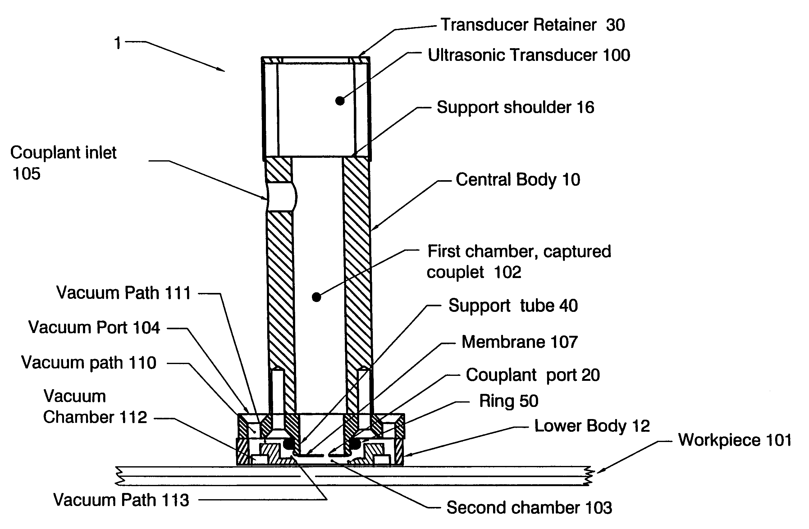
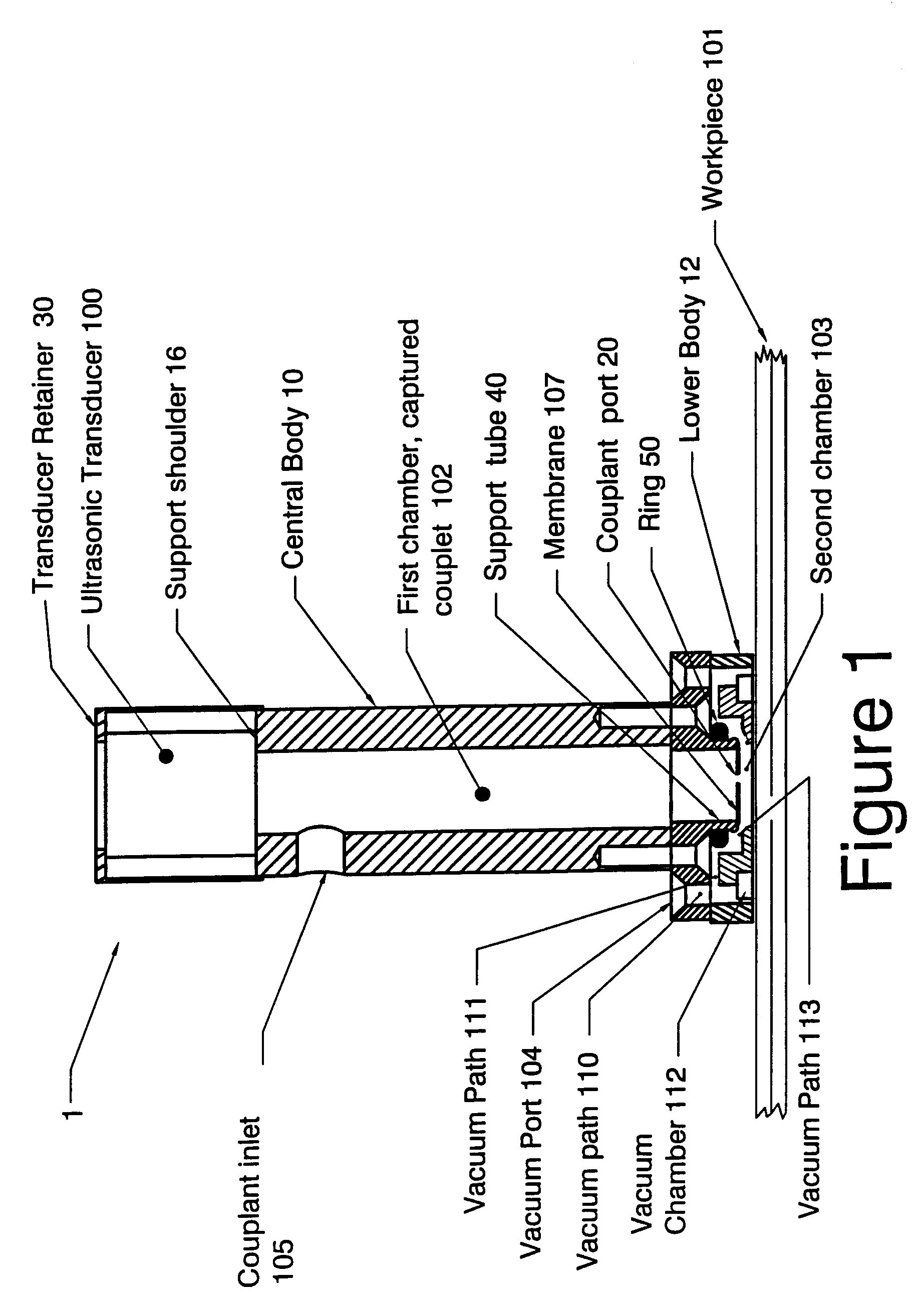
[0026]The present invention is an acoustic inspection device, namely one that includes a small localized couplant chamber (smaller than the prior art) to wet the workpiece, eliminating the need to place the workpiece in an immersion bath. Additionally, the present invention has a small footprint, exposes the workpiece to less contaminants than prior art devices, provides rapid coupling to the workpiece and requires less couplant than prior art devices. These features overcome the shortcomings of a full range of prior art ultrasonic transducers that normally require complete or partial immersion of the workpiece during examination and scanning operations.

[0027]The following description is provided for a preferred embodiment of the present invention. Those skilled in the art will appreciate that various changes and modifications can be made to the discussed preferred embodiment while remaining within the scope of the present invention.

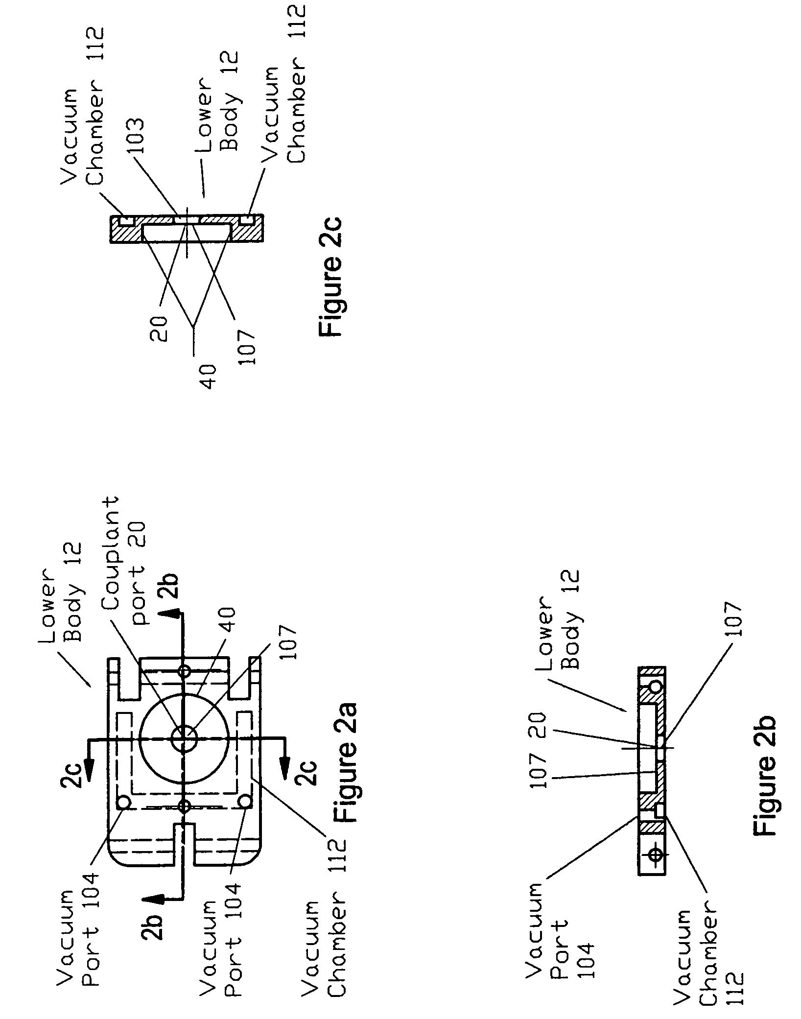
[0028]That embodiment of the present invention is ...


PUM

PropertyMeasurementUnit
diameteraaaaaaaaaa
heightaaaaaaaaaa
frequenciesaaaaaaaaaa

Abstract

A lightweight apparatus for performing ultrasonic immersion inspection of a workpiece in an arbitrary orientation that uses significantly less couplant and has a reduced footprint size while providing ultrasonic performance levels comparable to those typically reached using immersion tanks, bubblers, or Dripless Bubblers™ while accommodating large and small ultrasonic beamwidths. The apparatus can be used with manual, automated, or electronic scanning techniques. The apparatus provides a quickly enabled ultrasonic coupling means that minimizes the area of the part wetted, and also can recover spent couplant. As a result, this reduces the number and type of contaminates to which the workpiece is exposed when used when compared to prior art immersion tanks and bubblers.

Description

BACKGROUND OF THE INVENTION[0001]1. Field of the Invention[0002]An acoustic inspection device, namely one that has a small footprint, exposes the workpiece to few contaminants, rapidly establishing coupling with the workpiece, requires less couplant than earlier devices, and a small localized couplant chamber to wet the workpiece without placement in an immersion bath.[0003]2. Description of the Prior Art[0004]Nondestructive Inspection (NDI) determines the quality of a workpiece without causing damage to the workpiece. One prior art NDI technique uses acoustic waves to inspect a workpiece: this technique directs an incident acoustic wave at a workpiece and analyzes the reflection to determine the workpiece's quality. Acoustic inspection is helpful, for example, to determine the integrity of airplane components including the wing, fuselage and empennage by detecting disbanded lap-splices, corroded rivet joints, and similar structural defects. Acoustic inspection is also helpful, for ...

Claims


Application Information

Patent Timeline
Patent Type & Authority Patents(United States)
IPC IPC(8): G01N29/28
CPCG01N29/07G01N29/28G01N2291/2638G01N2291/101G01N2291/044
Inventor FLEMING, MARVIN F.
Owner FLEMING MARVIN F
Why Eureka
Try Eureka