Ultrasound diagnostic apparatus

a diagnostic apparatus and ultrasonic technology, applied in diagnostics, ultrasonic/sonic/infrasonic data transmission, medical science, etc., can solve the problems of affecting the distance between the power supply part set around the diagnostic apparatus and the power receiving part of the ultrasound probe, and the need to suspend ultrasonic diagnosis,

Inactive Publication Date: 2012-08-02
FUJIFILM CORP
View PDF3 Cites 38 Cited by
  • Summary
  • Abstract
  • Description
  • Claims
  • Application Information

AI Technical Summary

Benefits of technology

[0013]The invention has been made in order to solve such related-art problems, and an object thereof is to provide an ultrasound diagnostic apparatus that can continue ultrasonic diagnosis for a prolonged period of time, without damaging the operativity of an ultrasound probe.
[0014]Additionally, another object of the invention is to provide an ultrasound diagnostic apparatus that can also acquire a high image-quality ultrasound image if required for diagnosis.
[0015]Moreover, still another object of the invention is to provide an ultrasound diagnostic apparatus that has a simple structure, and can perform heat dissipation of the ultrasound probe without damaging the operativity of the ultrasound probe.

Problems solved by technology

However, in the apparatus of JP 2002-530175 A, in order to house the ultrasound probe in the probe holder of the apparatus body to charge the battery, there is a concern that ultrasonic diagnosis may need to be suspended when this battery is charged, and the ultrasonic diagnosis may be hindered.
In the apparatus of JP 2010-233826 A, there is a concern that the distance between the power supply part set around the diagnostic apparatus and the power receiving part of the ultrasound probe may change according to an operator's standing position, or that it may become impossible to efficiently supply electric power to the ultrasound probe due to the influence of electronic devices or the like around the ultrasound diagnostic apparatus.
Additionally, even if an operator desires a high image-quality ultrasound image as being obtained in the non-power-saving mode during diagnosis in the power-saving mode, it is difficult to make a change to the non-power-saving mode from the balance with the exhaustion of the battery.
Additionally, the related-art ultrasound diagnostic apparatuses have also a problem regarding the generation of heat by the ultrasound probe.
However, in such an apparatus, there is a problem in that the cooling medium circulation unit needs to be mounted on the probe connector part of the diagnostic apparatus body, and the ultrasound diagnostic apparatus is complicated.
Additionally, since the cooling medium pipe is formed along the cable that connects the diagnostic apparatus body and the ultrasound probe, the diameter of the cable increases and the flexibility of the cable deteriorates, and therefore, there is a concern that the operativity that is an important performance for the ultrasound probe may be adversely affected.

Method used


Image

  • Ultrasound diagnostic apparatus
  • Ultrasound diagnostic apparatus
  • Ultrasound diagnostic apparatus

Examples


embodiment 1

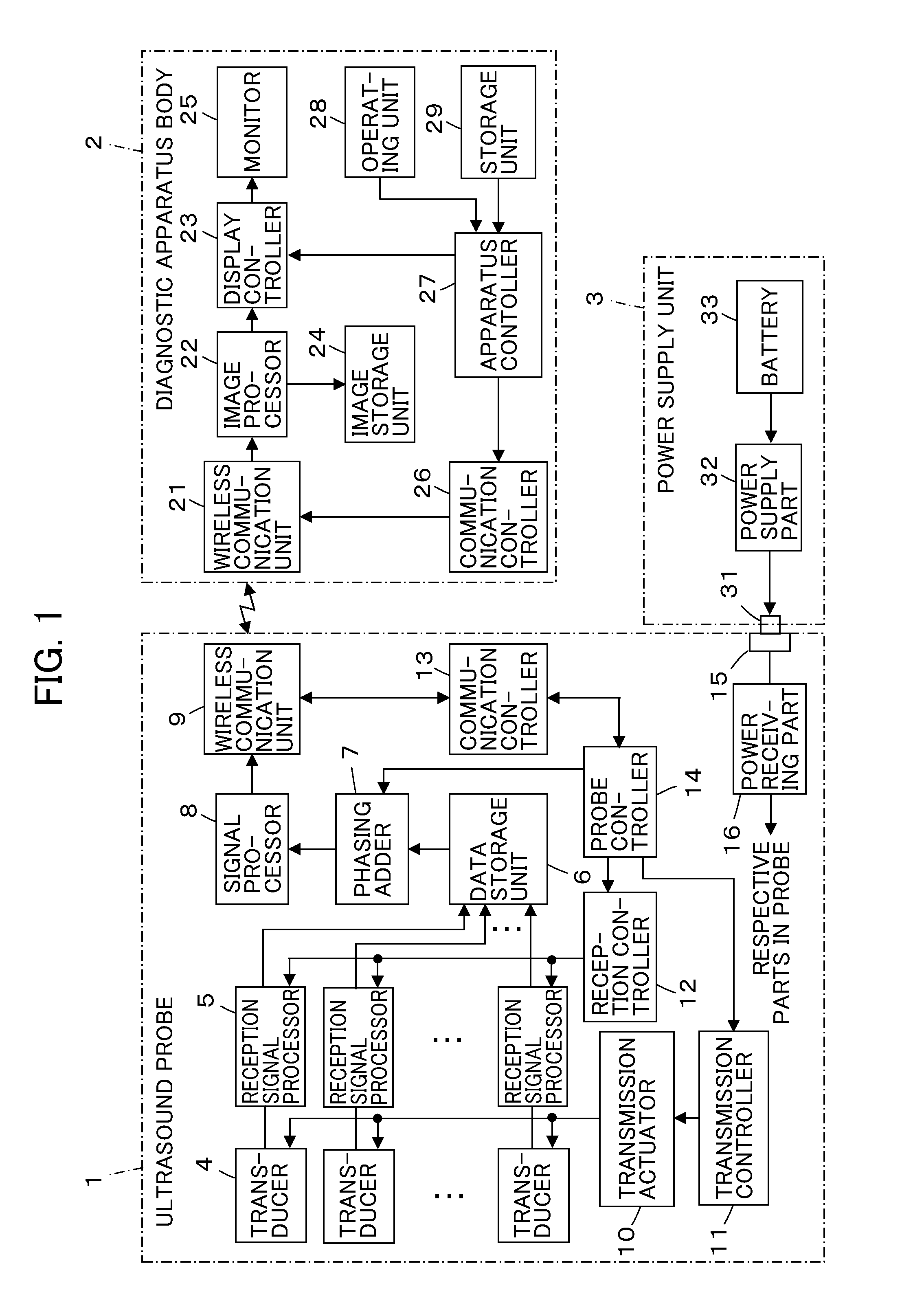
[0060]FIG. 1 shows the configuration of an ultrasound diagnostic apparatus related to Embodiment 1 of the invention. The ultrasound diagnostic apparatus includes an ultrasound probe 1, a diagnostic apparatus body 2 connected to the ultrasound probe 1 by wireless communication, and a power supply unit 3 detachably connected to the ultrasound probe 1.

[0061]The ultrasound probe 1 has a plurality of ultrasound transducers 4 that constitute a plurality of channels for a one-dimensional or two-dimensional transducer array, reception signal processors 5 are connected to the transducers 4 so as to correspond to the transducers, respectively, and a wireless communication unit 9 is connected to the reception signal processors 5 via a data storage unit 6, a phasing adder 7, and a signal processor 8 sequentially. Additionally, a transmission controller 11 is connected to the plurality of transducers 4 via a transmission actuator 10, a reception controller 12 is connected to the plurality of rec...

embodiment 2

[0090]FIG. 5 shows an ultrasound probe 41 related to Embodiment 2. The ultrasound probe 41 has a plurality of power receiving terminals 15a, 15b, etc. at mutually different positions, such as the top face, bottom face, and lateral face of the housing 41a, and the power receiving terminals 15a, 15b, etc. are connected to the power receiving part 16 in the ultrasound probe 41, respectively. The other internal configuration of the ultrasound probe 41 is the same as that of the ultrasound probe 1 in Embodiment 1.

[0091]Since the plurality of power receiving terminals 15a, 15b, etc. is disposed at mutually different positions of the housing 41a, an operator can appropriately connect the power supply terminal 31 of the glove 34 to a power receiving terminal that is most easily connected according to a method of gripping the ultrasound probe 41, and the operativity of the ultrasound probe 41 can be improved while performing power supply.

[0092]In addition, in this case, it is preferable that...

embodiment 3

[0093]FIG. 6 shows an ultrasound probe 51 related to Embodiment 3. The ultrasound probe 51 has a flexible cable 52 for power reception pulled out to the outside from the housing 51a, and a power receiving terminal 15c is arranged at a distal end of the cable 52 for power reception. The power receiving terminal 15c is connected to the power receiving part 16 in the ultrasound probe 51 via the cable 52 for power reception. In addition, in other respects, the internal configuration of the ultrasound probe 51 is the same as that of the ultrasound probe 1 in Embodiment 1.

[0094]By arranging the power receiving terminal 15c at the distal end of the flexible cable 52 for power reception pulled out to the outside from the housing 51a, the power receiving terminal 15c can be located in a free position and orientation with respect to the housing 51a of the ultrasound probe 51, and it is possible to further improve the operativity of the ultrasound probe 51 while performing power supply.

[0095]I...


PUM


Abstract

An ultrasound diagnostic apparatus comprises: an ultrasound probe that has a transducer array transmitting an ultrasonic beam toward a subject and receiving an ultrasonic echo by the subject to output reception signals; a diagnostic apparatus body that is connected to the ultrasound probe by wireless communication and generates an ultrasound image on the basis of the reception signal output from the transducer array; at least one power receiving terminal that is arranged at the ultrasound probe and electrically connected to respective parts in the ultrasound probe; and a power supply unit that is capable of being attached to an operator's body and is detachably connected to the power receiving terminal so as to perform power supply to the respective parts in the ultrasound probe.

Description

BACKGROUND OF THE INVENTION[0001]The present invention relates to an ultrasound diagnostic apparatus, and particularly, to a power supply method to an ultrasound probe of an ultrasound diagnostic apparatus that performs diagnosis on the basis of an ultrasound image generated by transmitting and receiving ultrasonic waves from a transducer array of the ultrasound probe.[0002]The present invention also relates to measures against heat dissipation of the ultrasound probe.[0003]In the related art, ultrasound diagnostic apparatuses using an ultrasound image are being put into practical use in the medical field. Generally, this type of ultrasound diagnostic apparatus has an ultrasound probe with a built-in transducer array, and an apparatus body connected to this ultrasound probe. Ultrasonic waves are transmitted toward a subject from the ultrasound probe, and the ultrasound probe receives ultrasonic echoes from the subject and generates an ultrasound image by electrically processing rece...

Claims


Application Information

Patent Timeline
Patent Type & Authority Applications(United States)
IPC IPC(8): A61B8/13
CPCA61B8/42A61B8/56A61B8/4472A61B8/4209
Inventor NAKAMURA, KENJI
Owner FUJIFILM CORP
Why Eureka
Try Eureka