Method and system for free space optical tomography of diffuse media

a diffuse medium and optical tomography technology, applied in the field of tomography, can solve the problems of reducing the versatility reducing the efficiency of direct contact systems, and absorbing light when passing through objects

Active Publication Date: 2006-08-03
THE GENERAL HOSPITAL CORP
View PDF31 Cites 64 Cited by
  • Summary
  • Abstract
  • Description
  • Claims
  • Application Information

AI Technical Summary

Benefits of technology

[0017] In accordance with the present invention, a system and a method to generate an image by optical tomography of internal structures of an object, such as a body part, includes a surface capture system to capture a surface model (e.g., a mathematical description) of the surface of the object and to provide the surface model to one or more optical models. The optical models can be used to account for propagation of the light toward light sensors, which can be spaced apart from the object.
[0018] In accordance with the present invention, a system for optical tomography of an object includes a data collection system to collect light having traveled through the object and in free space about the object and to generate one or more signals in response to the light. The system also includes a surface-capture system to receive surface light reflected from a surface of the object and to generate a surface model (e.g., a three-dimensional mathematical description) of at least a portion of the surface of the object. The system further includes a model processor coupled to the surface-capture system to provide one or more optical models associated with the surface of the object. A solution processor coupled to the data collection system and the model processor provides a tomographic image of the object in response to the one or more signals and to the one or more optical models. In one particular embodiment, the data collection system includes one or more light sources for emitting light directed to propagate through the object and one or more light sensors dis

Problems solved by technology

As is known, a signal received by a single energy sensor (i.e., at one angle) does not contain sufficient information to generate either a two-dimensional or a three-dimensional representation of internal structures of the object.
However, unlike x-ray tomography, for which x-rays tend to pass through an object in a straight line with relatively little attenuation, light tends to be absorbed and to scatter

Method used


Image

  • Method and system for free space optical tomography of diffuse media
  • Method and system for free space optical tomography of diffuse media
  • Method and system for free space optical tomography of diffuse media

Examples


Embodiment Construction

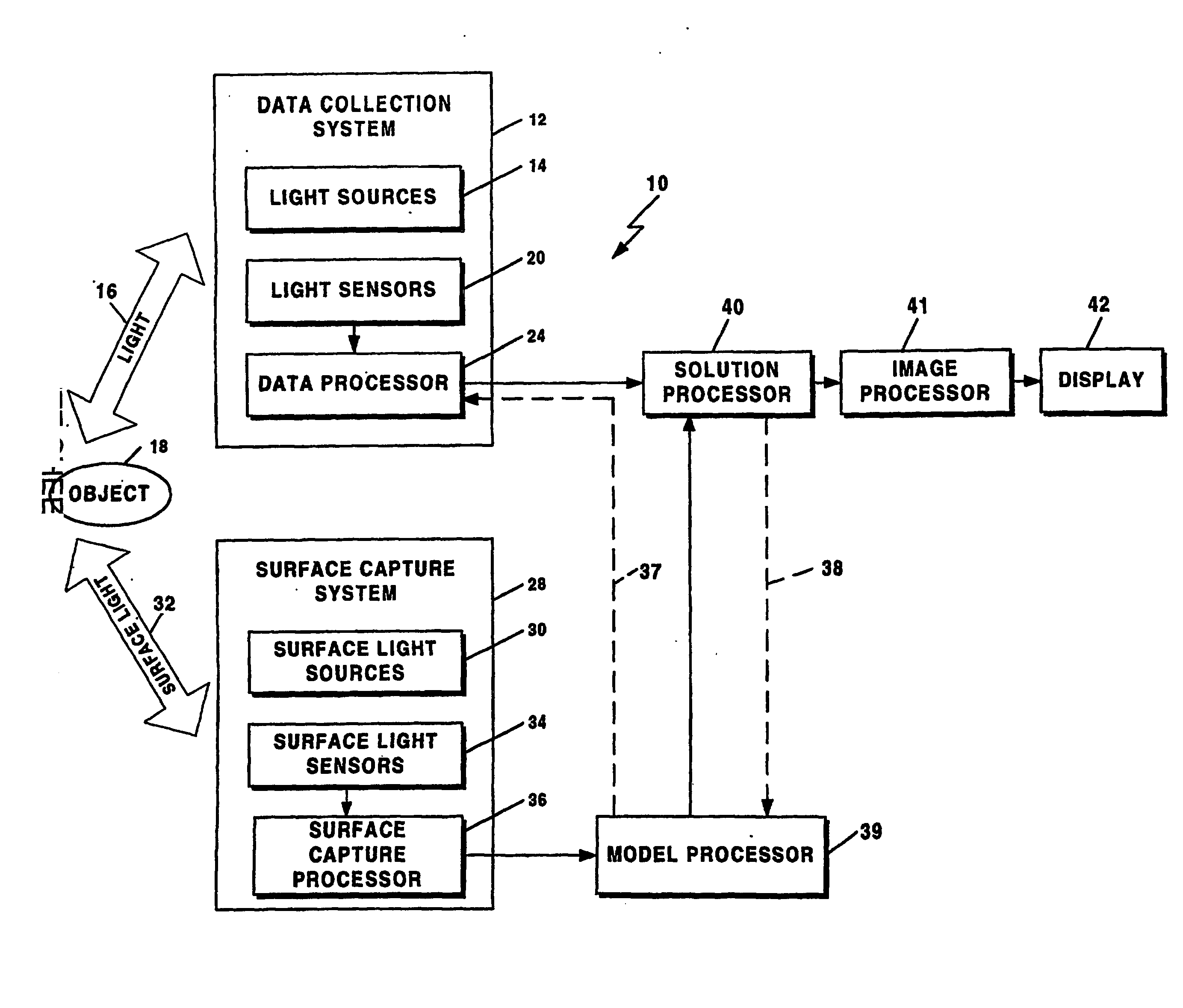
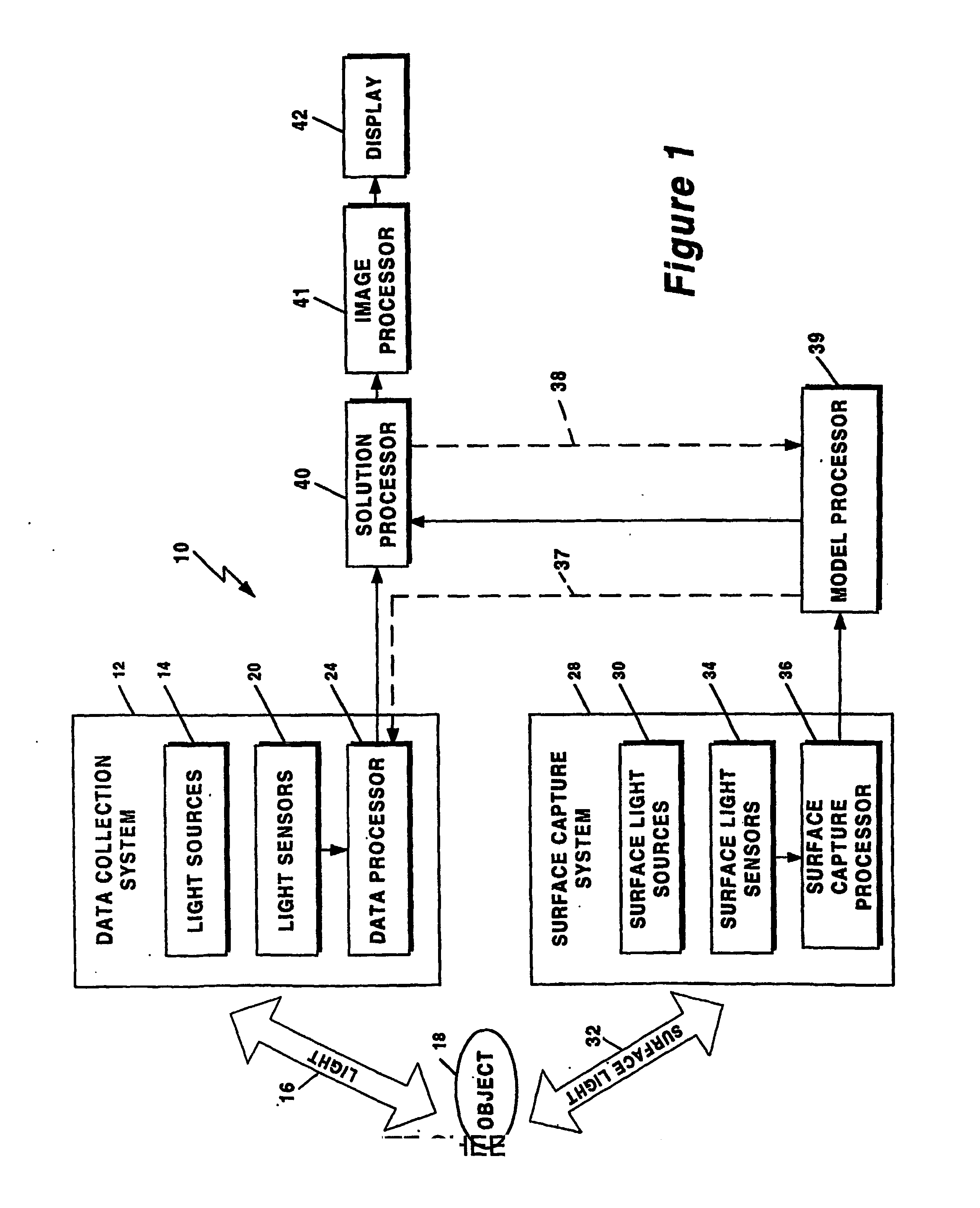
[0039] Referring now to FIG. 1, an optical tomography system 10 includes a data collection system 12 having one or more light sources 14 spaced from an object 18 under test. Each of the one or more light sources 14 projects light 16 toward the object 18. Portions (not shown) of the light 16 which pass through the object 18 are received by one or more light sensors 20 which are disposed proximate, but spaced apart from, the object 18. It should be appreciated that sensors 20 are disposed about the object 20 such that the sensors 20 can receive light, which propagates through the object 18. In one particular exemplary embodiment, the light sensors 20 are disposed to be approximately one centimeter apart from the object 18, proximate a side of the object 18 which is substantially opposite from the side of the object upon which the light 16 is directed. However, in other embodiments, the one or more light sensors 20 can be disposed more that one centimeter or less than one centimeter ap...


PUM


Abstract

A method and a system for free space optical tomography provides one or more light source and one or more light sensors spaced, which in one embodiment are spaced apart from and object to be imaged. A surface capture system coupled to a variety of optical models provides the method and system with the ability to render accurate tomographic images though the light has propagated both through a diffuse medium and, in on embodiment, also through free space to the one or more light sensors.

Description

CROSS REFERENCE TO RELATED APPLICATIONS [0001] This application claims the benefit under 35 U.S.C. §119(e) of U.S. Provisional Application No. 60 / 445,016 filed Feb. 5, 2003, which application is incorporated herein by reference in its entirety.STATEMENT REGARDING FEDERALLY SPONSORED RESEARCH [0002] Not Applicable. FIELD OF THE INVENTION [0003] This invention relates generally to tomography and, more particularly, to optical tomography. BACKGROUND OF THE INVENTION [0004] As is known in the art, tomography is often used in construction of detailed images of internal structures of objects. Tomography relies upon a selected form of energy being directed toward and passing through the object at more than one angle. The energy from the various angles is collected and processed to provide a tomographic image. The received signals are typically less intense (i.e., darker) where the object is thicker or more dense, and more intense (i.e., brighter) where the object is thinner or less dense. ...

Claims


Application Information

Patent Timeline
IPC IPC(8): A61B6/00A61B5/00A61B5/107G06T11/00
CPCA61B5/0066A61B5/0071A61B5/0073A61B5/1076A61B5/1077
Inventor NTZIACHRISTOS, VASILISRIPOLL, JORGE
Owner THE GENERAL HOSPITAL CORP
Why Eureka
Try Eureka