
Medical fluid delivery system and method relating to the same

a technology of medical fluid and delivery system, which is applied in the direction of positive displacement liquid engine, engine diaphragm, diaphragm valve, etc., can solve the problems of increasing the cost, size and weight of the device, the need for relatively complicated control circuitry, and the need for large weight and power requirements,

Inactive Publication Date: 2006-08-03
UNIVERSAL INFUSION TECH
View PDF99 Cites 62 Cited by
  • Summary
  • Abstract
  • Description
  • Claims
  • Application Information

AI Technical Summary

Benefits of technology

[0016] In one approach, the bi-directional drive member may be moved at a wide range of speeds (e.g., by changing the supplied current and / or voltage to electric bi-directional drive motor) and / or operated at intermittent times in both the first and second directions, thereby enabling the first and second outputs to vary in response thereto. Such speed variation and / or intermittent pump operation, thus, enables a pump interfaced with such bi-directional drive member to deliver medical fluids over a wide range of flow rates in corresponding relation to the first and second outputs.
[0099] In one aspect, portions of the disposable medical fluid line set, (e.g. valves and / or a manifold) may be placed in corresponding recesses provided in a housing. The valves may be placed in valve recesses and a portion of the disposable medical fluid line set may be placed to interface with a rotary peristaltic pump head. Once in the proper recesses, particular elements of the disposable medical fluid line set may be further held in place by closing a cover. One or more separate means may be provided to assist in maintaining the disposable medical fluid line set in its proper position in the housing.

Problems solved by technology

In order to achieve both types of movement, many devices must use two motors, one for the fast movement and another for the slow movement, thus increasing the cost, size and weight of the device.
However, stepper motors have numerous disadvantages, including high cost, the need for relatively complicated control circuitry, large size, large weight and high power requirements.
The disadvantages of presently available motor systems are particularly problematic in medical infusion pump systems.
Medical infusion pumps have typically employed stepper motors to provide rotational motive force, and thus are limited by the disadvantages of a stepper motor as listed above.
The use of multiple independent controllers or pumps, however, is disadvantageous for many reasons, including: the increased possibility of infection occasioned by multiple IV venipuncture; the increased discomfort to the patient, the considerable labor and time required for administering multiple IVs and setting up multiple controllers / pumps; the increased clutter around the patient; the comparatively high cost of procuring and maintaining several pumps; and the comparatively high cost incurred in maintaining an inventory of tubes required by each of the different pump types.
This arrangement may result in unintentional fluid flow to a patient when the valve set is mistakenly removed from or incorrectly aligned within the pump unit.
In some circumstances, operation of valves in accordance with the teachings of Epstein et al. is not desirable due to the resultant fluid interactions or fluid damage, such as cell damage to blood cells.

Method used


Image

  • Medical fluid delivery system and method relating to the same
  • Medical fluid delivery system and method relating to the same
  • Medical fluid delivery system and method relating to the same

Examples


Embodiment Construction

Definitions

For the purposes of the present invention, the following terms shall have the following meanings:

[0131] For the purposes of the present invention, “a” or “an” entity refers to one or more of that entity; for example, “a valve actuator” or “an pinch valve” refers to one or more of the components or at least one component. As such, the terms “a” or “an”, “one or more” and “at least one” can be used interchangeably herein. It is also noted that the terms “comprising,”“including,” and “having” can be used interchangeably. Furthermore, a component “selected from the group consisting of” refers to one or more of the components in the list that follows, including mixtures (i.e. combinations) of two or more of the components.

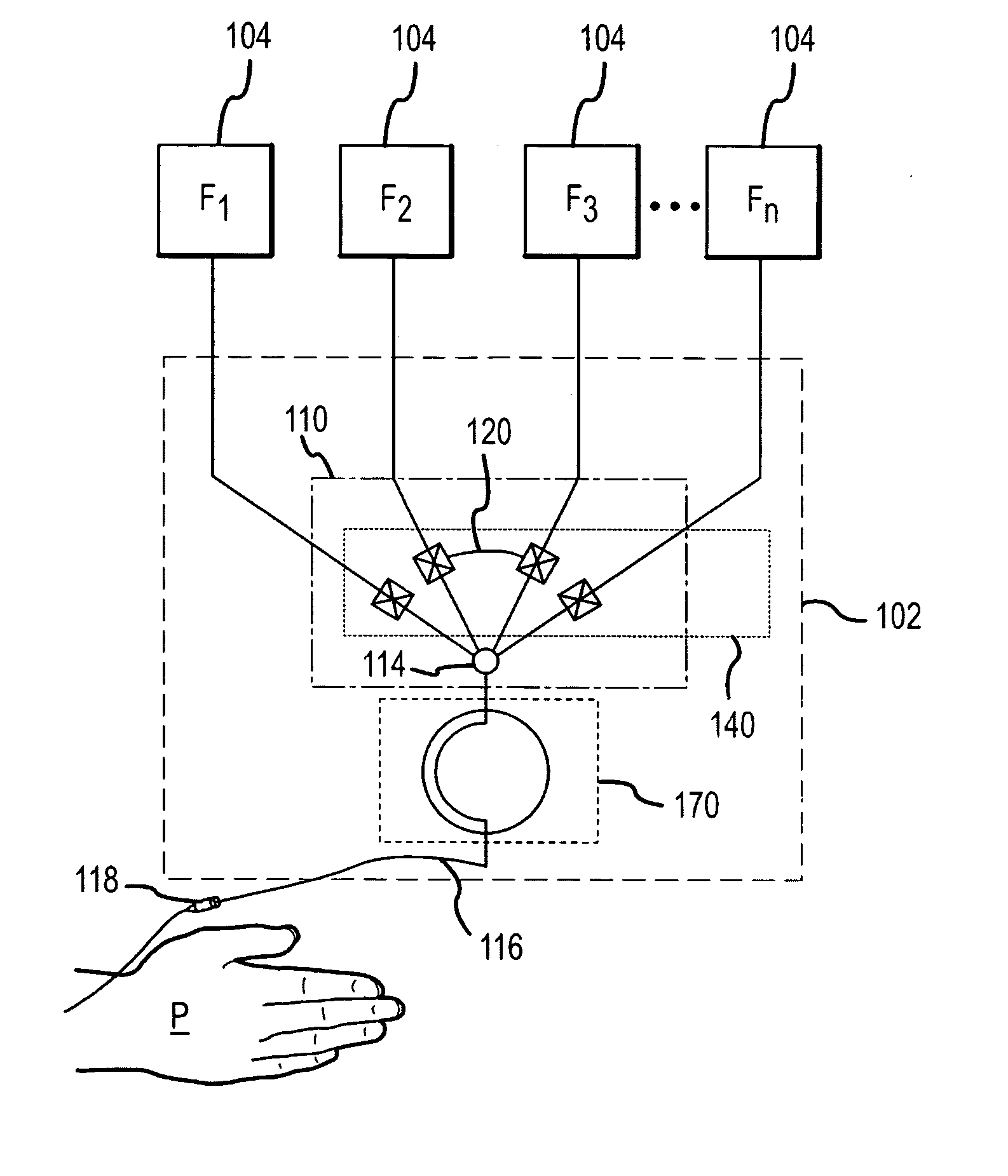
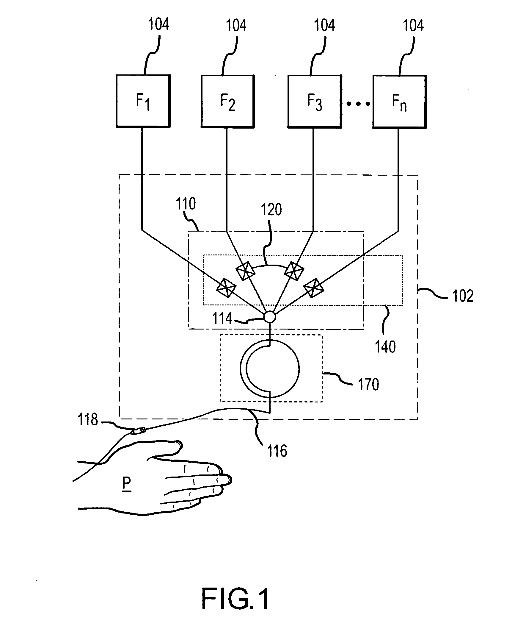
[0132] As used herein, a “pump” refers broadly to means for moving fluid. A pump may operate through changes in pressure and / or gravity. Pumps include but are not limited to rotary peristaltic pumps, linear peristaltic pumps, centrifugal pumps, diaphragm...


PUM


Abstract

A medical fluid delivery system for the use in the delivery of medical fluids. The medical fluid delivery system may include a pumping system, a disposable medical fluid line set and a valve operating system. The disposable tubing line set may include valves adapted to interface with the valve operating system. The valve operating system may be adapted to operate only selected valves using a single drive means. The pumping system may be operated over a wide range of medical fluid delivery rates by employing a bi-directional drive member and a transmission interfaced with the drive member and a pump.

Description

CROSS-REFERENCE TO RELATED APPLICATIONS [0001] This application claims priority to PCT Patent Application Serial No. US2004 / 023799 filed Jul. 23, 2004, entitled “DRIVE MOTOR TRANSMISSION SYSTEM”, which claims priority to U.S. Provisional Patent Application Ser. No. 60 / 489,401 filed Jul. 23, 2003, entitled “ELECTRIC DRIVE MOTOR TRANSMISSION SYSTEM”. The above-referenced patent applications are incorporated herein by reference as if their contents were set forth below in full.FIELD OF THE INVENTION [0002] This invention is generally directed to a drive motor system which operates over a wide range of speeds and torques through a novel arrangement of motion transfer members (e.g., gears and clutches), a bi-directional drive member (e.g., a bi-directional motor), which can be driven bi-directionally, and a transmission. In a particular application, the invention is directed to fluid pumping with a drive motor system that utilizes a bi-directional motor to achieve a range of fluid moveme...

Claims


Application Information

Patent Timeline
Patent Type & Authority Applications(United States)
IPC IPC(8): F04B53/00
CPCA61M5/16827A61M39/284F04B49/06Y10T137/0318Y10T137/87056Y10T137/87064Y10T137/87161
Inventor MALCOLM, DAVID R.
Owner UNIVERSAL INFUSION TECH
Features
  • Generate Ideas
  • Intellectual Property
  • Life Sciences
  • Materials
  • Tech Scout
  • Unparalleled Data Quality
  • Higher Quality Content
  • 60% Fewer Hallucinations
Learn More