Pulling cord winder for venetian blind

Inactive Publication Date: 2006-08-10
CHENG LI MING
5 Cites 7 Cited by

AI-Extracted Technical Summary

Problems solved by technology

Since the external pulling cord is usually exposed, children may play with the pulling cord for fun, and the pulling cord may hang a child's neck or even strangle the child and cause a fatal accident.
However, the venetian blind lifting mechanism A of this sort usually comes with a set of complicated components and a large housing because the venetian blind lifting mec...

Benefits of technology

[0009] Another objective of the present invention is to provide a pulling cord winder for a venetian blind that uses a rough surface of an arc pressing board disposed separately on both sides of the brake member to increase the friction for compressing the br...

Abstract

A pulling cord winder for a venetian blind is installed at the bottom of a lower rail of the venetian blind, and the pulling cord winder that winds or retrieves each pulling cord disposed separately on both sides of the venetian blind has two corresponding engaged upper and lower bases, two bracket coil wheels, a bracket, a brake member, and a push rod, such that when the push rod retreats and presses the brake member, a resilience of a drawspring pushes the rough surfaces of an arc pressing board on both sides of the brake member and the two bracket coil wheels into a compressed form or an open form as to brake and rotate the two bracket coil wheels and control the two brackets to lift or lower the venetian blind to a fixed position.

Application Domain

Technology Topic

Image

  • Pulling cord winder for venetian blind
  • Pulling cord winder for venetian blind
  • Pulling cord winder for venetian blind

Examples

  • Experimental program(1)

Example

[0022] To make it easier for our examiner to understand the objective of the invention, its structure, innovative features, and performance, we use a preferred embodiment and the attached drawings for the detailed description of the invention.
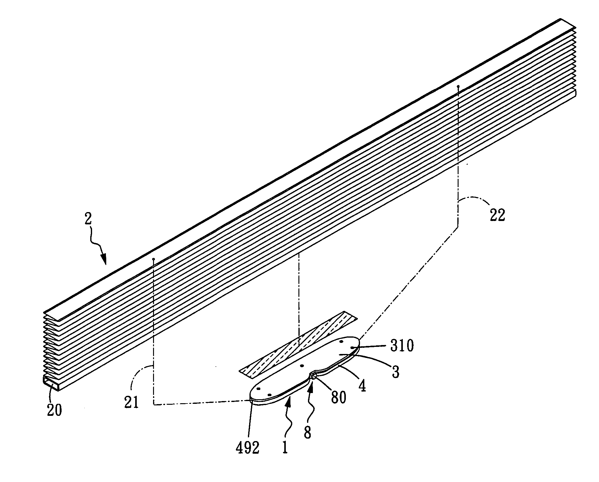
[0023] The basic assembly of a pulling cord winder for a venetian blind in accordance with the present invention is shown in FIGS. 5 and 6. The pulling cord winder 1 is installed directly at the bottom of a lower rail 20 of a venetian blind 2, and a pulling cord 21, 22 is disposed separately on both sides of the pulling cord winder 1. The pulling cord winder 1 comprises: an upper base 3 and a lower base 4 engaged with each other, a fixed cam 41; two bracket coil wheels 5 mounted onto a fixed cam 41, 42 corresponding to a chamber 40 at the center of the lower base 4, and a bracket 6 being disposed at the bracket coil wheel 5 and hooked by both embedding ends 60,61 therein; a brake member 7 clamped between the two bracket coil wheels 5 and hooked by a drawspring 71; and a push rod 8 passing the drawspring 71 and pressing the brake member 7, such that when the push rod 8 retreats and presses the brake member 7, a resilience of the drawspring 71 pushes an arc pressing board 70 separately disposed on both sides of the brake member 7 to compress the bracket coil wheel 5 into a compressed open form, and thus braking and rotating the two bracket coil wheels 5 and pressing or releasing the two brackets 5 to lift or lower the venetian blind to a fixed position.
[0024] The foregoing upper base 3 forms a long member with a recession 30 in the middle of the front end, and a burying hole 31, 32 is disposed on both distal ends and the middle of a lateral side of the upper base 3. An embedding member 34 is disposed separately on an attached surface at the front and rear ends of the upper base 3. An arc groove 340 is disposed in the middle of the embedding member 34 at the front end. The lower base 4 has a shape identical to that of the upper base 3 and a chamber 40 in the middle of the lower base 4 has a fixed cam 41, 42 corresponding to the latch groove 410, 420. A protruded rod 43 having a latch groove 430 is disposed on a lateral side in the middle of the two fixed cams 41, 42 and corresponding to the burying hole 32 disposed on a lateral side of the upper base 3. The two fixed cams 41, 42 comprise an arc blocking wall 44, 45 disposed at an external side, and the lower base 4 at its external side comprises a fastening rod 46 having a screw hole 460 and corresponding to the burying hole 31 of the upper base 3. The fastening rod 46 comprises a cam 47 being disposed at the central position of the fastening rod 46 and having an axle hole for connecting a guide wheel 48. The lower base 4 at the front and rear ends has an arc groove 49 and a recessed groove 491 corresponding to an arc groove 340 and an embedding member 34, and both ends have a perforation 492 for pulling or receiving a pulling cord 21, 22 from both sides of the Venetian blind. A latch member 493 having a perforation 494 is disposed on the internal side of a recessed surface of the arc groove 49. The two bracket coil wheels 5 has a containing space 50 at the top, and a sheathing hole 500 is disposed in the middle of the bottom end of the containing space 50. The sheathing hole 500 is connected to the fixed cams 41, 42 of the lower base 4. A blocking member 51 having a latch groove 510 is protruded from an internal edge of the containing space 50. A winding region 530 for winding the pulling cords 21, 22 on both sides of the venetian blind 2 is disposed between the protruded walls 52, 53 on both sides of the two bracket coil wheels 5.
[0025] Both embedding ends 60, 61 of the two brackets 6 are hooked respectively into the chamber 40 in the middle of the lower base 4 corresponding to the latch grooves 410, 420 of the fixed cams 41, 42 and into the latch groove 510 of the blocking member 51 of the two bracket coil wheels 5. An arc pressing board 70 is extended separately from both sides of the brake member 7; a rough surface 700 is disposed on the internal side of the arc pressing board 70; and the embedding groove 701 and protruded rod 702 are disposed at a front end and a top of the brake member7 respectively. A perforation 703 is disposed at the protruded rod 702 for inserting one end 710 of the drawspring 703. The other end 711 of the drawspring 71 is inserted into a perforation 494 of the latch member 493 of the lower base 4. A long hole 72 is disposed in the middle of the brake member 7 for passing through a protruded rod 43.
[0026] The push rod 8 at its end forms a pressing section 80, and the pressing section 80 is embedded in an embedding groove 701 at the front of the brake member 7.
[0027] The pulling cords 21, 22 on both sides of the venetian blind 2 are wound around the winding region 530 of the two bracket coil wheels during its assembly, such that the sheathing holes 500 of the two bracket coil wheels 5 are coupled with the fixed cams 41, 42 corresponding to the chamber 40 of the lower base 4. Both embedding ends 60, 61 of the two brackets 6 are latched respectively into the chamber 40 of the lower base 4 corresponding to the latch grooves 410, 420 and into the latch groove 510 of the blocking member 51 of the two bracket coil wheels 5. The long hole 72 in the middle of the brake member 7 sheathes onto the protruded rod 43 of the lower base 4. The perforation 703 of the protruded rod 702 at the front end of the top of the brake member 7 is hooked to one end 710 of the drawspring 71, and one end of the drawspring 71 passes through the perforation 494 of the latch member 493 of the lower base 4. The push rod 8 is embedded into the embedding groove 701 at the front end of the brake member 7 and installed at the arc groove 49 at the front end of the lower base 4. Finally, the embedded member 34 disposed at the front and read end of the upper base 3 is embedded into the recessed groove 491 corresponding to the lower base 4, and secured into the burying holes 31, 32 on both sides of the lower base 3 and in the middle of the lateral side and all the way to the screw holes 460 on the lower base 4 corresponding to the fastening rod 46 by a screw 310 and the latch groove 430 of the protruded rod 43 respectively to define a thinner pulling cord winder 1. The pulling cord winder 1 is attached at the bottom of a lower rail 20 of the venetian blind 2, such that the pulling cords 21, 22 on both sides of the venetian blind 2 are wound or released through the perforations 492 on both sides of the lower base 4 into the winding region 530 of the two bracket coil wheels 5. Thus, the thinner pulling cord winder 1 can reduce its weight as well as the force applied onto the internal drawspring 71 of the pulling cord winder 1. The overall pulling cord winder 1 is lighter and more convenient to be installed onto the bottom of the lower rail 20 at an end of the venetian blind 2.
[0028] Referring to FIG. 7 together with FIGS. 8A and 8B, the pressing section 80 of the push rod 8 is pressed (or withdrawn) directly during its operation, and the arc pressing boards 70 on both sides of the brake member 7 also move backward. In meanwhile, the drawspring 71 installed at the external edge of the push rod 8 compresses the rough surfaces 700 on both sides of the arc pressing boards 70, and the originally compressed pulling cords 21, 22 in the winding region 53 of the two bracket coil wheel 5 are in an open form (or compressed form), so that the two bracket coil wheels 5 can rotate or brake and the two brackets 6 can be compressed or released so as to lift or lower the venetian blind. However, if it is necessary to pull or rewind the venetian blind 2, the pressing section 80 of the push rod 8 is released, and a resilience of the drawspring 71 at the external edge of the push rod 8 acts as an individual brake of the brake member 7. Therefore, the brake member 7 will not be disabled when the pulling cords 21, 22 are pulled excessively or insufficiently and a gap is resulted, and thus the Venetian blind 2 can be pulled or wound to a desired height.
[0029] Referring to FIGS. 9 and 10, if the venetian blind 2 is pulled to a fully opened state, the pulling cords 21, 22 in the winding region 530 of the two bracket coil wheels 5 will be outwardly pulled all the way to the end, and the winding region 530 of the two bracket coil wheel 5 is pressed and fixed by the increased friction of the rough surfaces 700 of the arc pressing boards 70 on both sides of the brake member 7, so that the two bracket coil wheels 5 will not fall off.

PUM

no PUM

Description & Claims & Application Information

We can also present the details of the Description, Claims and Application information to help users get a comprehensive understanding of the technical details of the patent, such as background art, summary of invention, brief description of drawings, description of embodiments, and other original content. On the other hand, users can also determine the specific scope of protection of the technology through the list of claims; as well as understand the changes in the life cycle of the technology with the presentation of the patent timeline. Login to view more.

Similar technology patents

Shopping list attachment and holder for a shopping cart or basket

ActiveUS20160207557A1Better secure its attachmentIncrease frictionCarriage/perambulator accessoriesVehicle bodiesPaper sheetShopping basket
Owner:GALS SHOPPER

Split tube belay device

InactiveUS20070187176A1Reduce brake hand forceIncrease frictionSafety beltsMountaineeringMechanical engineering
Owner:CHRISTIANSON TONY

Classification and recommendation of technical efficacy words

  • Increase friction

Blood collection system for collecting blood from a body part for diagnostic purposes

ActiveUS20070260272A1Increase frictionPrevent oscillationCatheterDiagnostic recording/measuringPuncturingBlood collection
Owner:ROCHE DIABETES CARE INC

Lead obstacle-crossing robot walking device

ActiveCN101574983AIncrease frictionIncrease crawl angleManipulatorCable installation apparatusHigh voltage transmission linesEngineering
Owner:CHINA ELECTRIC POWER RES INST +1
Why Eureka
Try Eureka