Methods of improving stability of a vehicle using a vehicle stability control system

a technology of stability control system and vehicle, which is applied in the direction of vehicular safety arrangement, pedestrian/occupant safety arrangement, tractors, etc., can solve the problems of low-profile sports cars, suvs with independent suspension systems and roll stability control systems may still have a higher tendency to roll over than most cars, and the vehicle is usually more prone to rollover accidents than cars. to achieve the effect of improving the turning stability of the vehicle and improving the stability of the vehicl

Inactive Publication Date: 2006-08-10
HAMM ALTON B
View PDF56 Cites 19 Cited by
  • Summary
  • Abstract
  • Description
  • Claims
  • Application Information

AI Technical Summary

Benefits of technology

[0018] In accordance with yet another aspect of the present invention, a method of improving turning stability of a vehicle, the vehicle comprising a sprung mass portion, a first-side suspension for a first-side wheel, and a second-side suspension for a second-side wheel, is provided. This method includes the following steps described in this paragraph. The order of the steps may vary, may be sequential, may overlap, may be in parallel, and combinations thereof, if not otherwise stated. At least one condition of the vehicle is sensed. A first-side one-way mechanism and a second-side one-way mechanism are activated for a first period of time after the at least one condition is sensed to be exceeding a certain threshold level, wherein the first-side one-way mechanism is mechanically coupled to the first-side suspension, and wherein the second-side one-way mechanism is mechanically coupled to the second-side suspension. While the first-side and second-side one-way mechanisms are activated, allowing the first-side wheel to move toward the sprung mass portion of the vehicle to further compress the first-side suspension, allowing the second-side wheel to move toward the sprung mass portion of the vehicle to further compress the second-side suspension, restricting further expansion of the first-side suspension, and restricting further expansion of the second-side suspension.
[0019] In accordance with still another aspect of the present invention, a method of improving turning stability of a vehicle, the vehicle comprising a sprung mass portion, a first-side suspension for a first-side wheel, and a second-side suspension for a second-side wheel, is provided. This method includes the following steps described in this paragraph. The order of the steps may vary, may be sequential, may overlap, may be in parallel, and combinations thereof, if not otherwise stated. At least one condition of the vehicle is sensed. A first-side one-way mechanism and a second-side one-way mechanism are activated for a first period of time after the at least one condition is sensed to be exceeding a certain threshold level, wherein the first-side one-way mechanism is mechanically coupled to the first-side suspension, and wherein the second-side one-way mechanism is mechanically coupled to the second-side suspension. While the first-side and second-side one-way mechanisms are activated, and while the vehicle is turning, allowing the suspension of the first-side and second-side suspensions that is on an outside of a turn to further compress using its respective one-way mechanism, and restricting the other suspension of the first-side and second-side suspensions that is on an inside of the turn from expanding further.

Problems solved by technology

However, such vehicles are usually more prone to rollover accidents than cars.
Even SUVs with independent suspension systems and roll stability control systems may still have a higher tendency to roll over than most cars.
Even a low profile sports car may rollover when colliding with a trip mechanism.
Statistics show that over 90% of trip rollovers are caused by a loss of control of the vehicle.
When a driver swerves to one side (e.g., right) to avoid an object and then attempts to regain control of the vehicle and avoid going off the road by swerving in the opposite direction (e.g., left), this maneuver may cause a vehicle to rollover as well (even when no trip mechanism is encountered).
The vehicle in less than one second can be put into a precarious position that can cause the driver to panic as he feels his inability to control the vehicle.
This can quickly cause the driver to lose the ability to avoid other vehicles as well as curbs or abutments that can cause a rollover.

Method used


Image

  • Methods of improving stability of a vehicle using a vehicle stability control system
  • Methods of improving stability of a vehicle using a vehicle stability control system
  • Methods of improving stability of a vehicle using a vehicle stability control system

Examples


first embodiment

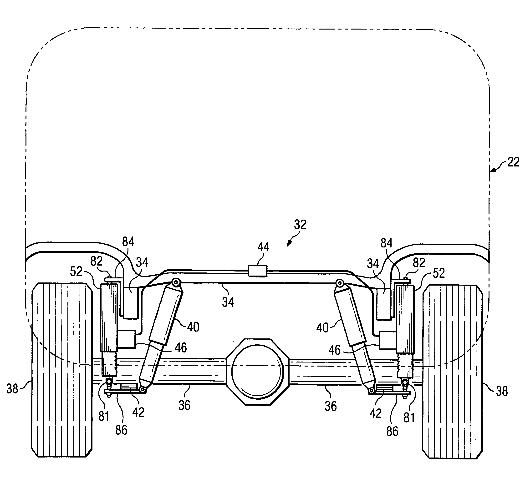
[0059]FIGS. 5-7 show various portions and various views of a first illustrative embodiment of the present invention. FIG. 5 is a rear view of an SUV 22 having a vehicle stability control system 32 installed thereon, in accordance with the first illustrative embodiment of the present invention. Portions of the vehicle 22 are not shown or are shown in dashed lines to better illustrate the system 32 of the In FIG. 5, the following portions of the vehicle 22 are shown: part of the frame 34, the rear transaxle 36, the rear tires 38, the rear shocks 40, and a cross-section view of the rear springs 42.

[0060] A system 32 of a preferred embodiment includes a signal generating device, a triggering device, a movable tongue system, and a ratchet mechanism. In the first embodiment, an electrical device 44 includes a signal generating device and a triggering device. The electrical device 44 is electrically coupled to a movable tongue system 46. The signal generating device of the first embodimen...

sixth embodiment

[0088]FIG. 25 illustrates a set of teeth 64 and a tongue member 54 of a sixth illustrative embodiment of the present invention. Only part of the system 32 of the sixth embodiment is shown, for purposes of simplifying the drawing. In FIG. 25, the tongue member 54 is larger and has multiple teeth 108, rather than just one “tooth” (i.e., the end of the tongue member 54). FIG. 25 illustrates that the tongue member 54 may be larger and that the tongue member 54 may have one or more teeth 108 formed therein or formed thereon. It is further contemplated that in an embodiment (not shown) of the present invention the tongue member 54 may have a series of teeth 108 (as in FIG. 25, or more) and the shaft member 71 may have only one tooth 64 or pin or tongue extending therefrom adapted to engage with the teeth 108 on the tongue member 54 to provide a ratcheting effect when engaged.

[0089]FIG. 26 is a side view showing part of a seventh embodiment of the present invention. In the seventh embodime...


PUM


Abstract

A method of limiting expansion of a spring member on a vehicle, wherein the spring member is biased between a sprung mass portion of the vehicle and an unsprung mass portion of the vehicle is provided. This method includes the following steps described in this paragraph. The order of the steps may vary, may be sequential, may overlap, may be in parallel, and combinations thereof, if not otherwise stated. At least one condition of the vehicle is sensed. A one-way mechanism is activated for a first period of time after the at least one condition is sensed to be exceeding a certain threshold level. Further expansion of the spring member is prevented or restricted or hindered using the one-way mechanism while the one-way mechanism is activated, but the activated one-way mechanism allowing the spring member to be further compressed.

Description

CROSS-REFERENCE TO RELATED APPLICATIONS [0001] This application is a continuation-in-part of U.S. patent application Ser. No. 11 / 065,942, entitled “Vehicle Stability Control System,” filed on Feb. 25, 2005, which application is incorporated herein by reference and which application claims the benefit of U.S. Provisional Application No. 60 / 547,703, filed on Feb. 25, 2004, entitled VEHICLE STABILITY SYSTEM, and U.S. Provisional Application No. 60 / 598,990, filed on Aug. 5, 2004, entitled VEHICLE STABILITY CONTROL SYSTEM, such provisional applications also hereby being incorporated herein by reference. [0002] This application relates to the following co-pending and commonly assigned patent applications: [0003] (1) U.S. patent application Ser. No. 11 / 066,634, entitled “Vehicle Stability Control System”, filed on Feb. 25, 2004, and now issued as U.S. Pat. No. ______; [0004] (2) PCT Patent Application Serial No. PCT / US2005 / 006194 and Publication No. WO 2005 / 082068 A3, entitled “Vehicle Sta...

Claims


Application Information

Patent Timeline
Patent Type & Authority Applications(United States)
IPC IPC(8): B60G21/05B60G17/016B60G25/00B62D49/08B60G17/00B60G99/00
CPCB60G7/006B60G7/02B60G17/005B60G17/0152B60G17/0162B60G2202/42B60G2204/143B60G2204/46B60G2204/4604B60G2800/0122B60G2800/24
Inventor HAMM, ALTON B.
Owner HAMM ALTON B
Why Eureka
Try Eureka