Induction motor having reverse-rotation preventing function

Inactive Publication Date: 2006-08-10
LG ELECTRONICS INC
View PDF9 Cites 16 Cited by
  • Summary
  • Abstract
  • Description
  • Claims
  • Application Information

AI Technical Summary

Benefits of technology

[0019] Therefore, an object of the present invention is to provide an induction motor having a reverse-rotation preventing function configured not only to preven

Problems solved by technology

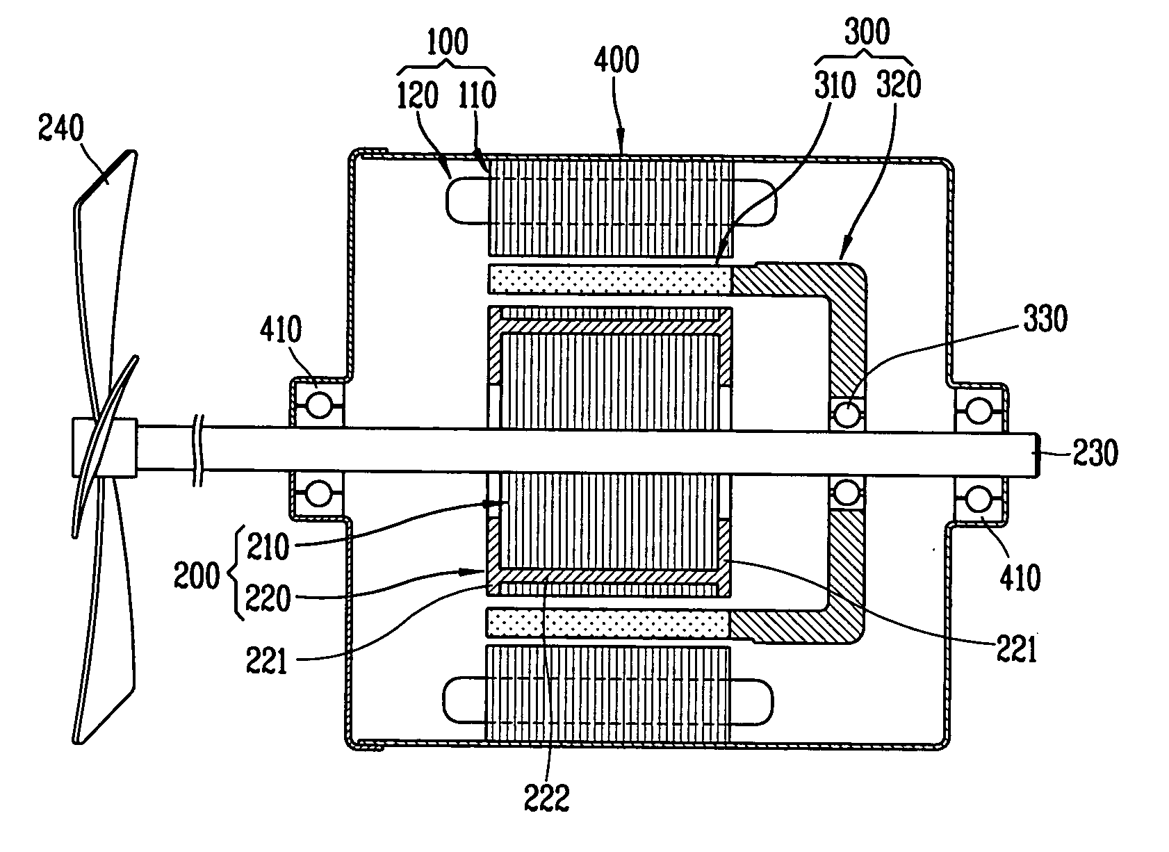
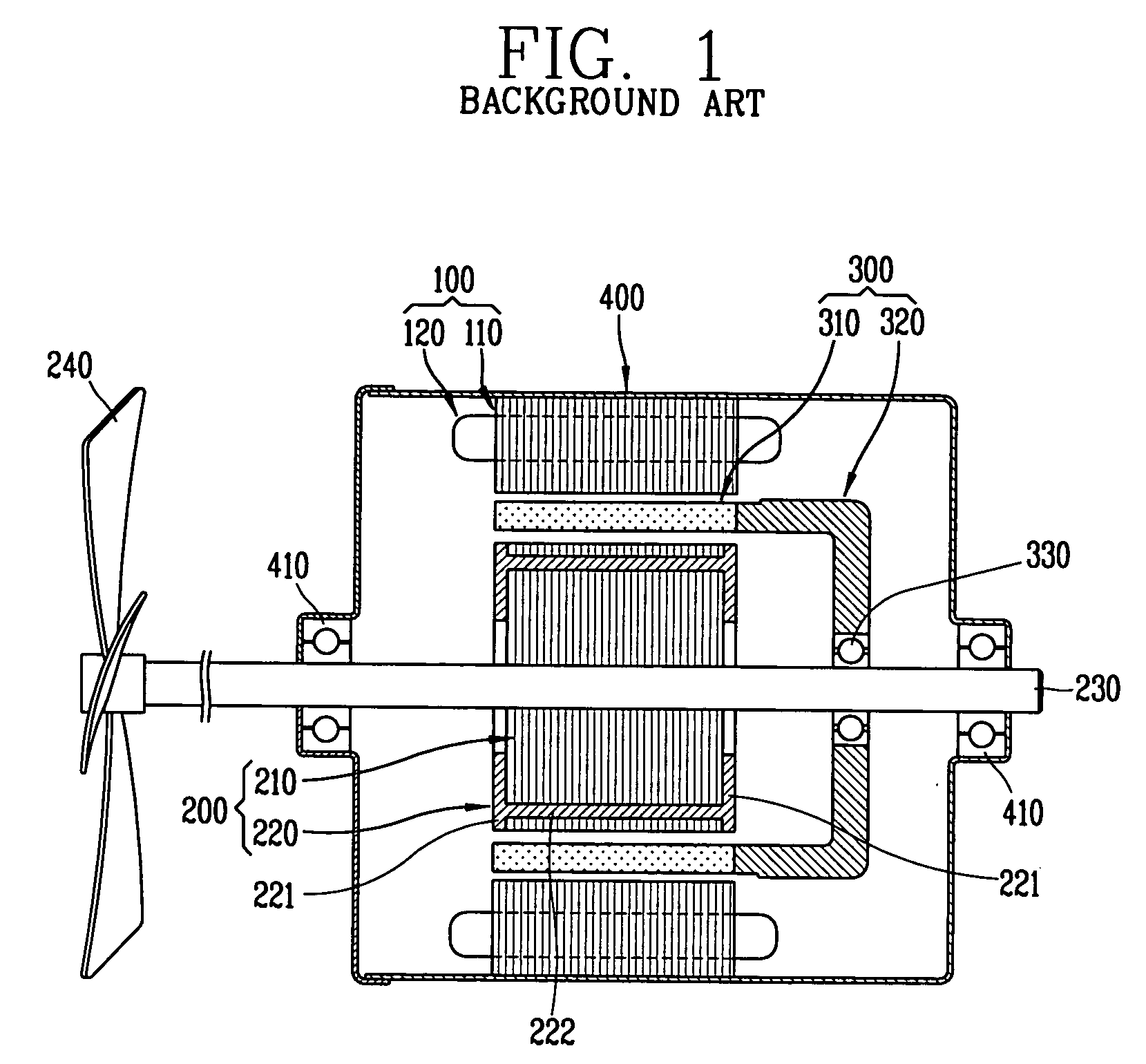
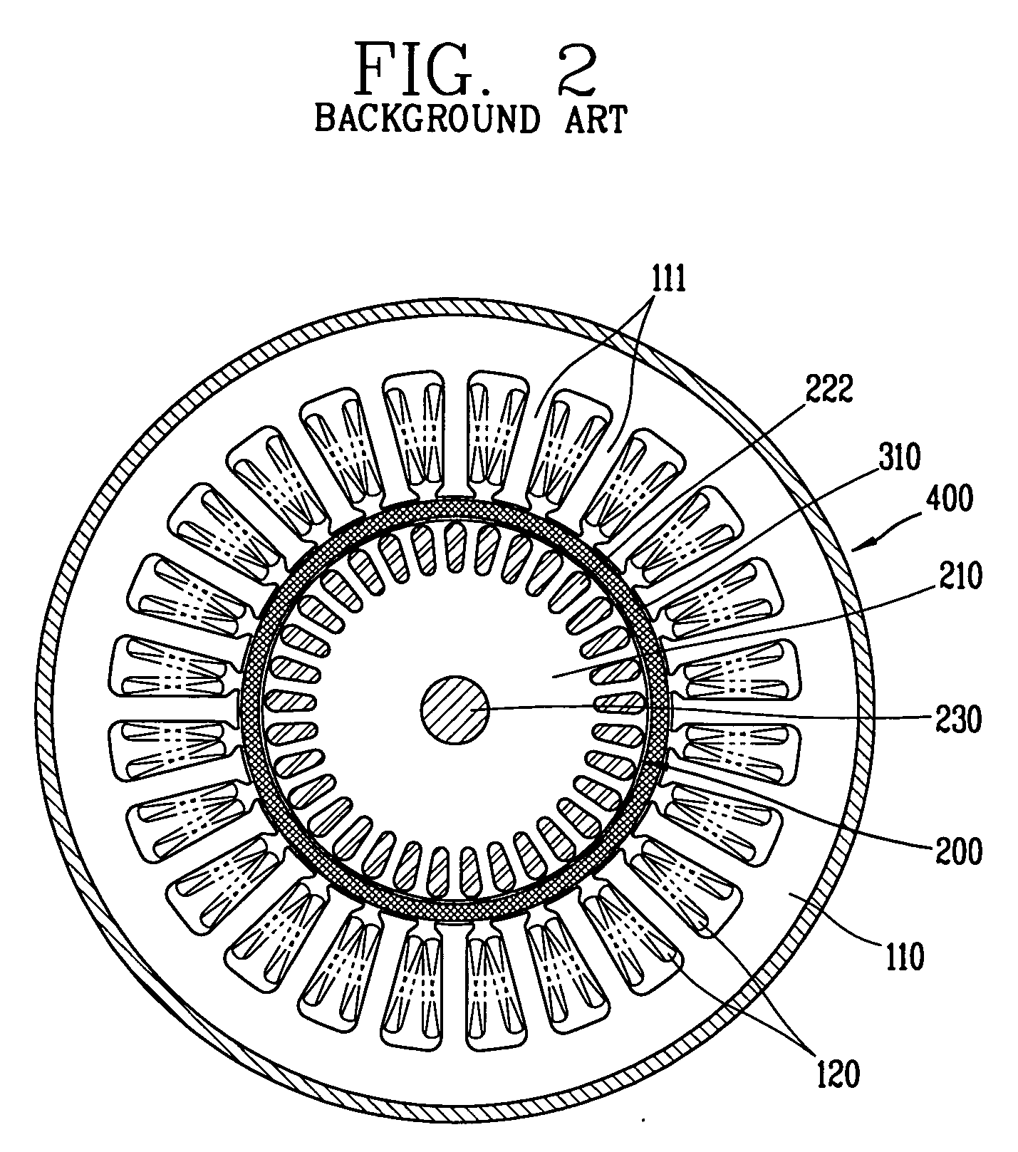
However, such an induction motor has disadvantages in that the synchronous rotor 300 and the induction rotor 200 make a reverse rotation under the influence of a voltage phase and unparallel rotating magne

Method used


Image

  • Induction motor having reverse-rotation preventing function
  • Induction motor having reverse-rotation preventing function
  • Induction motor having reverse-rotation preventing function

Examples


Example

[0057] In the first embodiment of the induction motor having a reverse-rotation preventing function according to the present invention, when a reverse-rotation force is applied to the induction rotor 600 due to a phase of a voltage which is initially applied or an unparallel rotating magnetic force at the time of initial driving of the motor, the synchronous rotor 700 is integrally coupled to the induction rotor 600, thereby increasing load inertia and thusly preventing a reverse rotation.

[0058] Also, only a small number of components are required for the rotation preventing unit and its structure becomes simple because the components for preventing the reverse rotation occurring when a reverse-rotation force is applied to the induction rotor 600 due to a phase of a voltage initially applied at the time of initial driving of the motor or due to an unparallel rotating magnetic force are the cage 610, the plurality of stopping protrusions 810 and stopping projections 820, and the lik...

Example

[0076] In the second embodiment of the induction motor having a reverse-rotation preventing function according to the present invention, when a reverse-rotation force is applied to the induction rotor 600 due to a phase of a voltage which is initially applied or an unparallel rotating magnetic force at the time of initial driving of the motor, the synchronous rotor 700 is integrally coupled to the induction rotor 600, thereby increasing load inertia and thusly preventing a reverse rotation.

[0077] Also, only a small number of components are required for the rotation preventing unit and its structure becomes simple because components for preventing the reverse rotation occurring when a reverse-rotation force is applied to the induction rotor 600 due to a phase of a voltage applied at the time of initial driving of the motor or due to an unparallel rotating magnetic force are the cage 610, the plurality of stopping protrusions 810 and stopping projections 820, and the like.

[0078] Als...


PUM


Abstract

An induction motor having a reverse-rotation preventing function, comprises: a stator provided with a winding coil generating flux by a current; an induction rotor provided with a cage and rotatably inserted in the stator, wherein a rotary shaft is coupled to its inside; a synchronous rotor provided with a permanent magnet and rotatably coupled between the stator and the induction rotor; an induction-force generating unit generating a force for moving the synchronous rotor in an axial direction; and a rotation preventing unit preventing a reverse rotation by fixing the synchronous rotor moved by the induction-force generating unit at the time of reverse rotation of the synchronous rotor. When a reverse rotation of the induction motor occurs as a reverse-rotation force is applied to the induction rotor due to a phase of a voltage which is initially applied and an unparallel rotating magnetic field at the time of initial driving of the motor, the load inertia of the synchronous rotor is increased, and the reverse rotation of the synchronous rotor and the induction rotor is prevented. Also, the construction for preventing the reverse rotation of the motor is simplified, and a small number of components are required.

Description

BACKGROUND OF THE INVENTION [0001] 1. Field of the Invention [0002] The present invention relates to an induction motor, and particularly, to an induction motor having a reverse-rotation preventing function configured not only to prevent a reverse rotation of a synchronous rotor and an induction rotor at the time of initial driving but also to simplify a structure and lower a manufacturing cost. [0003] 2. Description of the Background Art [0004] In general, a motor is for converting electric energy into kinetic energy, and is being used as a power source of various products such as home appliances. For example, in the case of a refrigerator, a motor rotates a fan to circulate the cool air within the refrigerator, and in the case an air-conditioner, the motor rotates a fan to let the cool air, which is formed by an evaporator, flow into a room. Also, there are various types of motors according to their fields of application. [0005] An induction motor, one of the various motors, inclu...

Claims


Application Information

Patent Timeline
IPC IPC(8): H02K17/00
CPCH02K7/1185H02K7/125H02K16/02H02K17/16H02K21/14
Inventor HAN, SEUNG-DOSHIN, HYOUN-JEONGAHN, JAE-HONGOH, SEUNG-SUKLEE, DONG-IL
Owner LG ELECTRONICS INC
Why Eureka
Try Eureka