Power hand tool

a hand tool and power technology, applied in the direction of screwdrivers, wrenches, lighting elements, etc., can solve the problems of low working efficiency, waste of time and labor, etc., and achieve the effect of improving working efficiency

Inactive Publication Date: 2006-08-10
MOBILETRON ELECTRONICS
View PDF12 Cites 28 Cited by
  • Summary
  • Abstract
  • Description
  • Claims
  • Application Information

AI Technical Summary

Benefits of technology

[0005] The present invention has been accomplished under the circumstances in view. It is the main object of the present invention to provide a power hand took, which greatly improves the working efficiency.

Problems solved by technology

This procedure wastes much time and labor, resulting in a low working efficiency.

Method used


Image

  • Power hand tool
  • Power hand tool
  • Power hand tool

Examples


Embodiment Construction

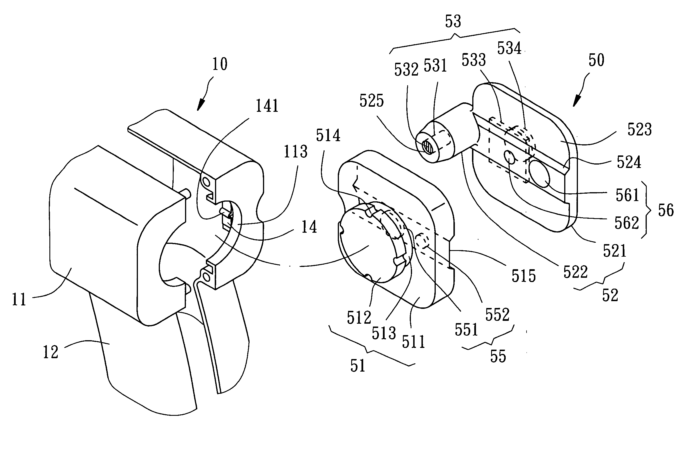
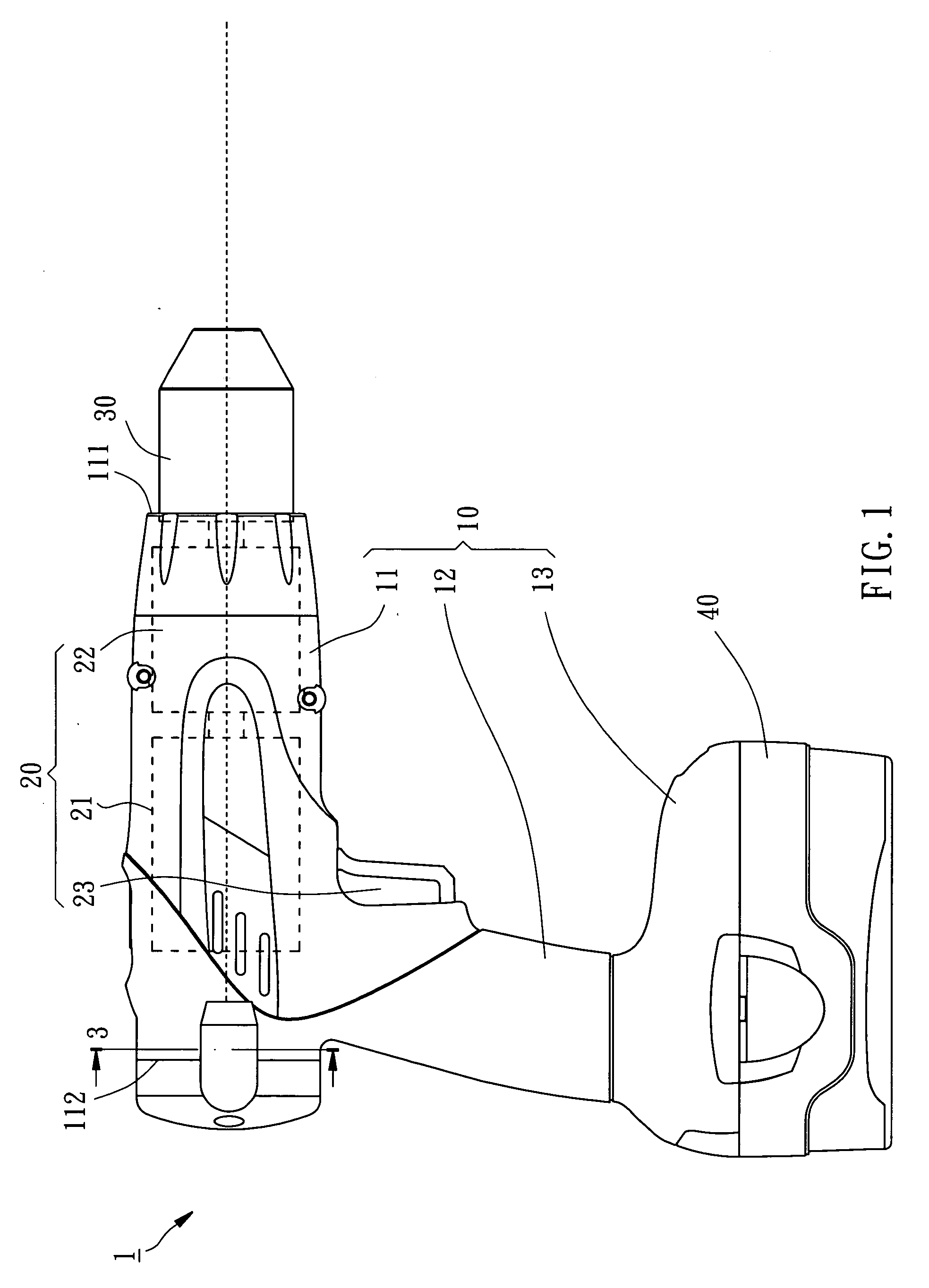
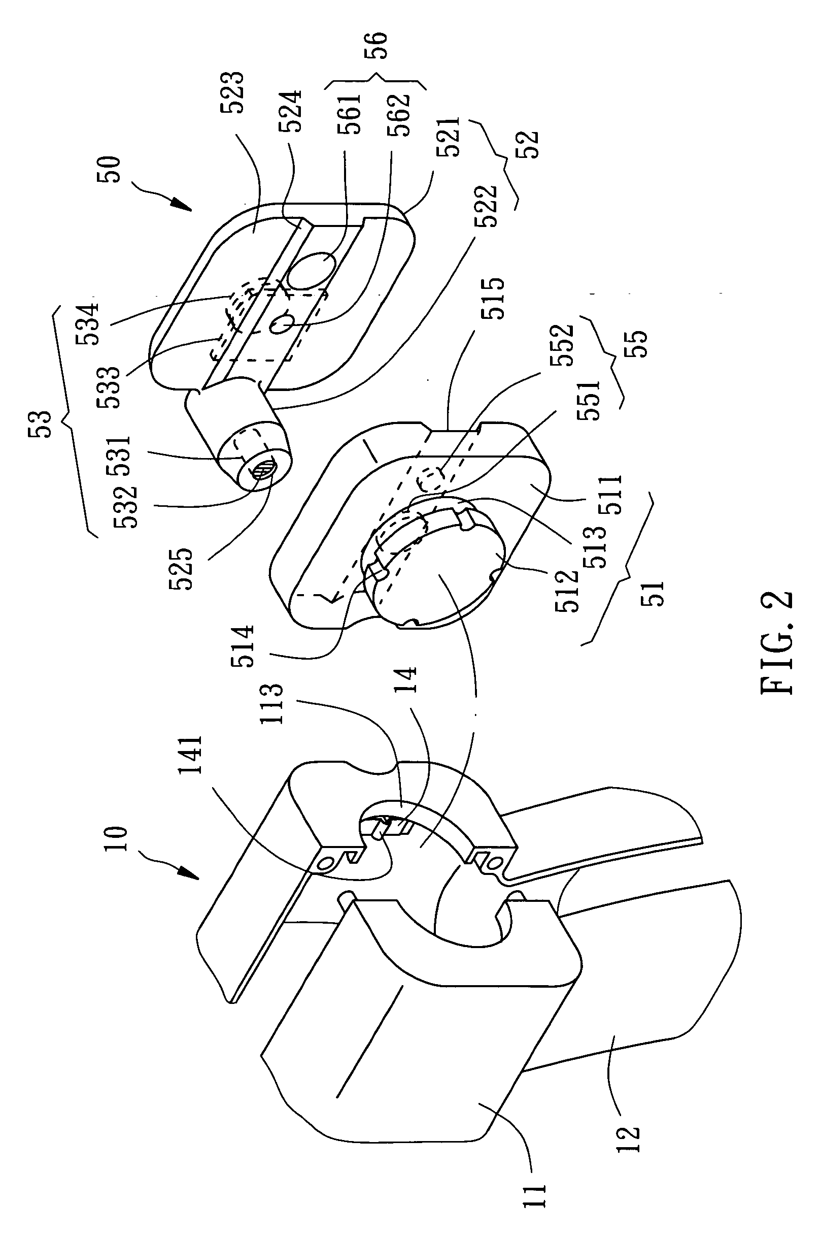
[0011] Referring to FIGS. 1-3 and 5, a power hand tool 1 in accordance with the preferred embodiment of the present invention is shown comprised of a housing 10, a driving device 20, a chuck 30, a battery pack 40, and a light projector 50.

[0012] The housing 10 is formed of a left-side cover shell and a right-side cover shell, comprising a body 11, a battery pack holder 13, and a grip 12 connected between the body 11 and the battery pack holder 13. The body 11 has a front end 111, a rear end 112, a circular opening 113 in the rear end 112, and two retaining spring strips 14 bilaterally symmetrically provided inside the body 11 adjacent to the circular opening 113. Each retaining spring strip 14 has a protruding portion 141.

[0013] The driving device 20 comprises a motor 21, a transmission gear set 22, and a control switch 23. The motor 21 and the transmission gear set 22 are mounted inside the body 11 of the housing 10. The control switch 23 is installed in the grip 12. The transmis...


PUM


Abstract

A power hand tool includes a housing, a chuck mounted in one end of the housing for holding a tool bit, a driving device mounted in the housing and coupled to the chuck for rotating the tool bit, and a light projector mounted in the housing for projecting a plane of light toward the extending direction of the tool bit to form a line of light on a working surface to be processed by the power hand tool.

Description

BACKGROUND OF THE INVENTION [0001] 1. Field of the Invention [0002] The present invention relates to a power hand tool and more particularly, to such a power hand tool, which is equipped with a laser projector that can be controlled to project a line of light on the workpiece to guide the operation of the power hand tool. [0003] 2. Description of the Related Art [0004] When wishing to drill a number of holes on a wall or workpiece along a line or to screw screws into the wall or workpiece, the operator must draw a line on the wall or workpiece before drilling or screwing. This procedure wastes much time and labor, resulting in a low working efficiency. SUMMARY OF THE INVENTION [0005] The present invention has been accomplished under the circumstances in view. It is the main object of the present invention to provide a power hand took, which greatly improves the working efficiency. [0006] To achieve this object of the present invention, the power hand tool comprises a housing, a driv...

Claims


Application Information

Patent Timeline
Patent Type & Authority Applications(United States)
IPC IPC(8): F21V33/00B25B23/18B25H1/00
CPCB25B23/18B25H1/0092B25F5/021
Inventor WU, CHIEN-CHUNTSAI, KIM Y.C.
Owner MOBILETRON ELECTRONICS
Why Eureka
Try Eureka