Packet communication apparatus

a communication apparatus and packet technology, applied in the field of packet communication apparatus, can solve the problems of inability to achieve the kind of throughput expected of the system, inability to achieve the average transmission tcp throughput above a certain level, and inability to achieve tcp throughpu

Inactive Publication Date: 2006-08-10
PANASONIC CORP
View PDF6 Cites 49 Cited by
  • Summary
  • Abstract
  • Description
  • Claims
  • Application Information

AI Technical Summary

Benefits of technology

[0042] The present invention is directed to solving these problems. It is therefore an object of the present invention to provide a packet communication apparatus that is capable of performing transmission restraint control of ACK packets so that, when the packet communication apparatus performs asymmetrical packet communication with a server, the server achieves average transmission TCP throughput tat is expected of the system.
[0043] According to one aspect of the present invention, a packet communication apparatus receives a data packet through a high speed receiving channel and transmits an ACK packet on a low speed transmitting channel on asymmetrical packet channels, and this packet communication apparatus has: a holder that holds a size of the ACK packet that is transmitted and a channel rate of the transmitting channel; a calculator that calculates an ACK packet generation interval based on the size of the ACK packet and the channel rate of the transmission channel; a counter that repeats counting the calculated ACK packet generation interval as one period and outputs an expiration signal every time the one period expires; and a transmitter that, every time the expiration...

Problems solved by technology

However, when packet communication is performed applying TCP to asymmetrical channels, according to the above-described communication steps, the problem arises that, server 903, after having transmitted data packets of the transmission window size, is unable to achieve the average trans...

Method used


Image

  • Packet communication apparatus
  • Packet communication apparatus
  • Packet communication apparatus

Examples


embodiment 1

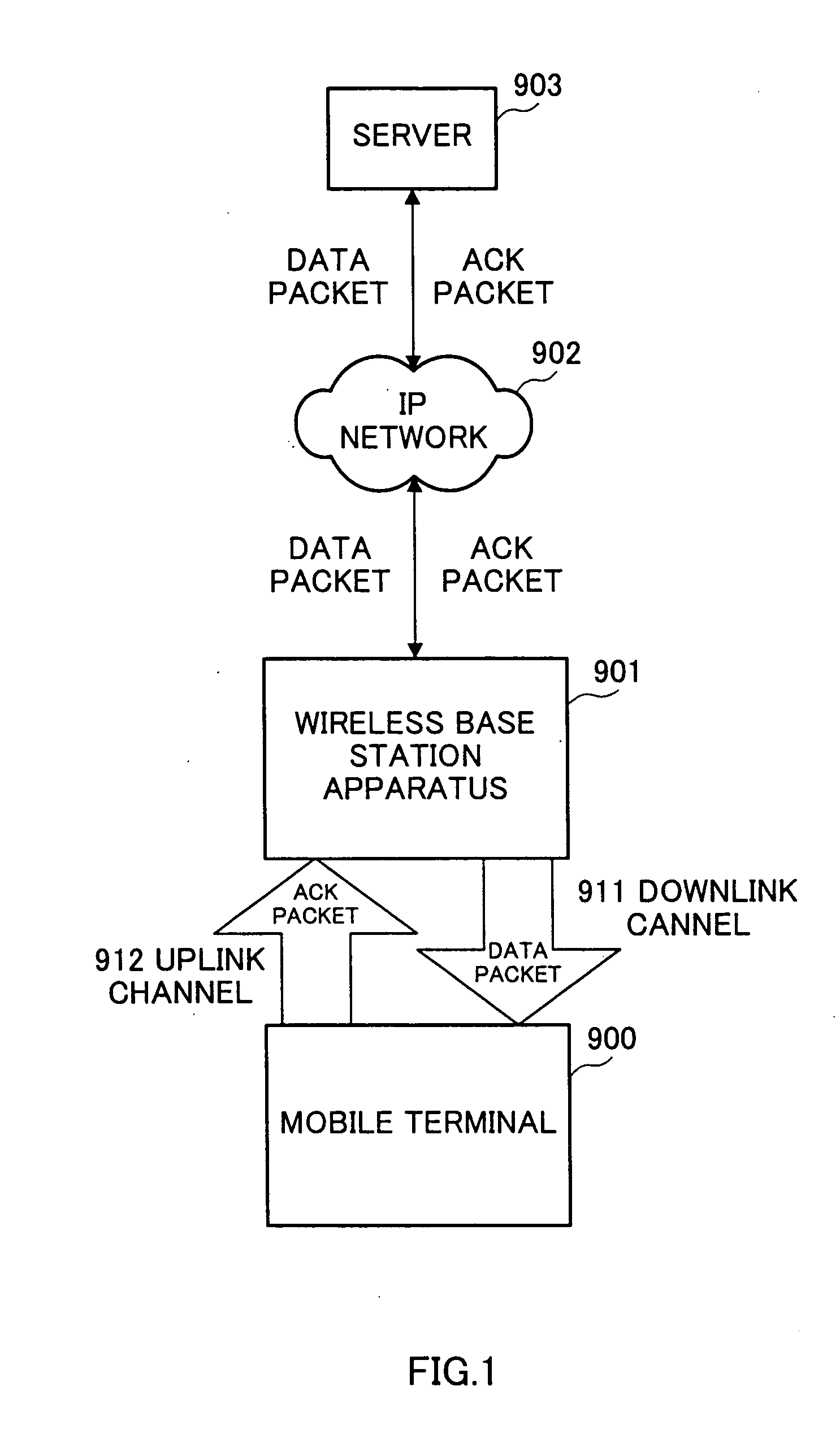
[0065]FIG. 7 is a block diagram showing a configuration of a mobile communication system used to explain the packet communication method according to Embodiment 1 of the present invention that applies TCP to asymmetrical channels.

[0066] In this mobile communication system, as shown in FIG. 7, mobile terminal 100 is connected to network (IP network) 102 that transfers packets using the Internet protocol (IP) via wireless base station apparatus 101. Server 103 is present in network (IP network) 102 and performs packet communication with mobile terminal 100 applying TCP to asymmetrical channels.

[0067] In other words, mobile terminal 100 receives a data packet transmitted from server 103 to IP network 102 via wireless base station apparatus 101, and returns an ACK packet to server 103 via wireless base station apparatus 101 and IP network 102. However, the channel rate of downlink channel 111 whereby mobile terminal 100 receives the data packet is greater than the channel rate of upli...

embodiment 2

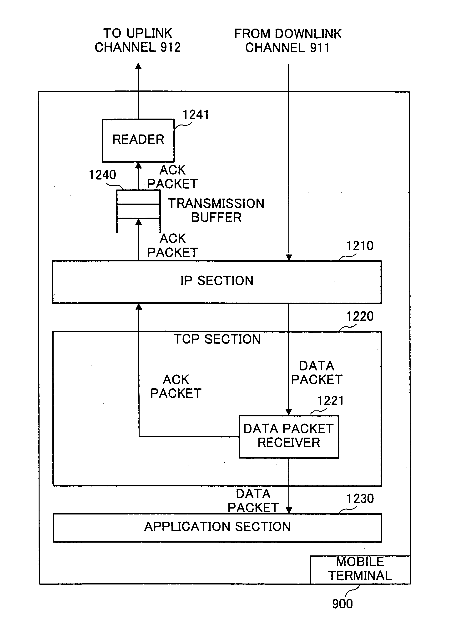
[0102]FIG. 12 is a block diagram showing a configuration of a mobile communication system used to explain the packet communication method according to Embodiment 2 of the present invention applying TCP to asymmetrical channels. Parts in FIG. 12 that are equivalent or identical to ones in the configuration shown in FIG. 7 will be assigned the same reference numerals. The following explanation will focus on parts specifically related to Embodiment 2.

[0103] The mobile communication system shown in FIG. 1 provides mobile terminal 600 instead of mobile terminal 100 to the configuration shown in FIG. 7. This mobile terminal 600 is configured as shown in FIG. 13.

[0104]FIG. 13 is a block diagram showing the configuration whereby the mobile terminal shown in FIG. 12 executes the packet communication according to Embodiment 2 applying TCP to asymmetrical channels. Parts in FIG. 13 that are equivalent or identical to ones in the configuration shown in FIG. 8 will be assigned the same referen...


PUM


Abstract

Mobile terminal 100 has: operator 251 that calculates the generation interval of ACK packets based on the size of the ACK packet that is to be transmitted and the channel rate of the transmitting channel, held in controller 250; delay ACK timer 223 that repeats counting the calculated ACK packet generation interval as one period and outputs an expiration signal every time the one period expires; and data packet receiver 221 that, every time the expiration signal is input, generates an ACK packet containing the latest reception confirmation information relating to data packets received while the expiration signal was being received, and transmits the ACK packet to transmission buffer 240 via IP section 210.

Description

TECHNICAL FIELD [0001] The present invention relates to a packet communication apparatus connected to asymmetrical packet communication channels adopting TCP (Transmission Control Protocol). BACKGROUND ART [0002] A case will be described here where a conventional method of packet communication in which asymmetrical communication channels adopt TCP is implemented in a mobile communication system. FIG. 1 is a block diagram showing the configuration of the mobile communication system. [0003] In this mobile communication system, as shown in FIG. 1, mobile terminal 900 is connected, via wireless base station apparatus 901, to network (i.e. IP network) 902 that transports packets using the internet protocol (IP). Server 903 is present on network (IP network) 902 and performs packet communication with mobile terminal 900 applying TCP to the asymmetrical communication channels. [0004] That is, mobile terminal 900 receives a data packet that server 903 transmits to IP network 902 via wireles...

Claims


Application Information

Patent Timeline
IPC IPC(8): H04J1/16H04Q7/24H04L12/56H04L12/54H04L1/18H04L13/08H04L29/06H04L29/08H04W28/10H04W80/06
CPCH04L1/1848H04W80/06H04L69/16H04L69/163
Inventor ISHIMORI, TAKAYUKIHIGUCHI, SHINICHIIIDA, KENICHIRO
Owner PANASONIC CORP
Why Eureka
Try Eureka