Image compressing apparatus that achieves desired code amount

Inactive Publication Date: 2006-08-10
RICOH KK
View PDF2 Cites 10 Cited by
  • Summary
  • Abstract
  • Description
  • Claims
  • Application Information

AI Technical Summary

Benefits of technology

[0018] According to another aspect of the invention, an apparatus for compressing an image includes a coding unit configured to generate code data by encoding data derived from image data, a memory unit which stores truncation data items identified by respective data sequence numbers, wherein a truncation data item specifies a way in which code data is removed from the generated code data, such that the larger the data sequence number, the higher a quality of a reproduced image obtained by decoding the generated code data after the removal of code data, or such that the larger the data sequence number, the lower the quality of the reproduced image, and a rate control unit configured to identify a data sequence number of a truncation data item that provides a code data parameter substantially equal to a desired value, the code data parameter being responsive to an amount of code data removal.
[0019] In the ap

Problems solved by technology

Depending on the way the data is removed, however, a reproduced image obtained after decoding of the code data may suffer significant degradation of image quality.
In this method, however,

Method used


Image

  • Image compressing apparatus that achieves desired code amount
  • Image compressing apparatus that achieves desired code amount
  • Image compressing apparatus that achieves desired code amount

Examples


first embodiment

(1) First Embodiment

[0042] (1-1) Outline of Data Removal

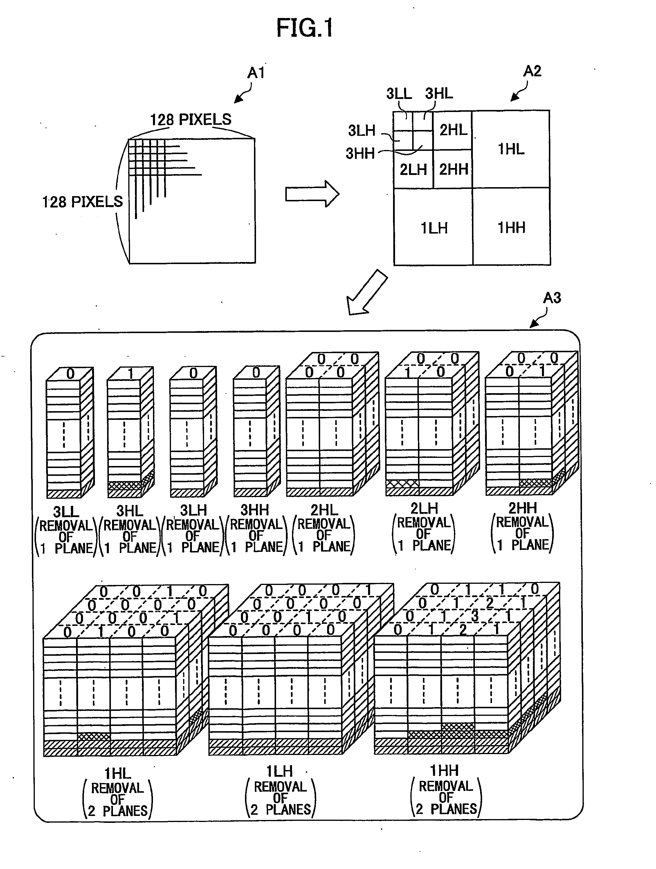
[0043]FIG. 1 is an illustrative drawing for explaining the removal of code data that is performed by an image compressing apparatus 100 (see FIG. 3) according to the first embodiment. An example to be examined here is a case in which image data having 128×128 pixels as indicated by an arrow A1 is encoded. First, the image data is converted into data of three color components Y, Cb, and Cr. Since each color component data is processed in the same manner, a description will be given only with respect to the processing of Y component data. Two-dimensional discrete wavelet transform is performed on the Y component data for the purpose of frequency analysis, producing 16-bit wavelet coefficients for sub-bands as indicated by an arrow A2 (i.e., 3LL, 3HL, 3LH, 3HH, 2HL, 2LH, 2HH, 1HL, 1LH, and 1HH). The wavelet coefficients are grouped into the respective sub-bands, and are further divided into 16 bitplanes. The wavelet coefficients ...

second embodiment

(2) Second Embodiment

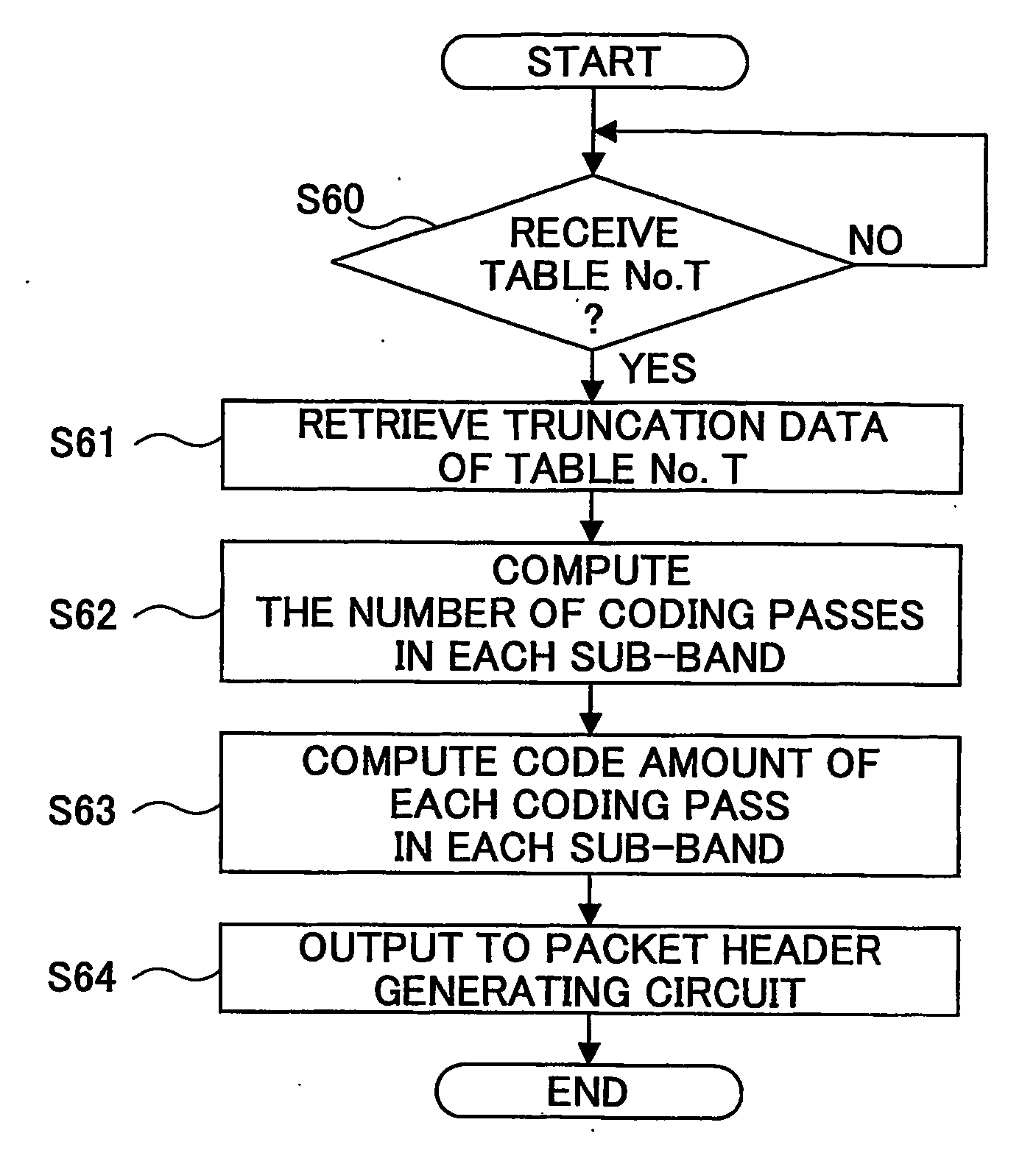
[0114]FIG. 13 is a block diagram showing the construction of an image compressing apparatus 200 according to the second embodiment. The image compressing apparatus 200 according to the second embodiment identifies optimum truncation data by comparing a total amount of code data with a desired code amount where the total amount of code data is obtained from a masking amount of each code-block of each sub-band and a code amount of each coding pass of each code-block. The total amount of code data is what remains after coding passes in each sub-band are removed based on the truncation data.

[0115] The construction of the image compressing apparatus 200 according to the second embodiment is basically the same as that of the image compressing apparatus 100 according to the first embodiment described above (see FIG. 3). In the following, a description will be given of a data-processing circuit 210 and a rate control circuit 220, which differ from those of the image co...

third embodiment

(3) Third Embodiment

[0135]FIG. 17 is a block diagram showing the construction of an image compressing apparatus 300 according to a third embodiment. Like the image compressing apparatus 100 of the first embodiment, the image compressing apparatus 300 identifies optimum truncation data by comparing a code-data removal amount with a desired code removal amount. In doing so, the code-data removal amount is obtained in all the sub-bands based on a masking amount of each code-block of each sub-band and a code amount of each coding pass of each code-block when coding passes are removed plane by plane in each sub-band based on the truncation data.

[0136] In the image compressing apparatus 100 of the first embodiment, a code amount (a change in the code data amount) that is removed when coding-pass code data are removed plane by plane with the lowest-order bitplane first in code-blocks of each sub-band is stored in the memory C or the memory D. Then, the code-data removal amount for all the...


PUM


Abstract

An apparatus for compressing an image, comprising: a coding unit configured to generate code data by encoding data derived from image data; a memory unit which stores truncation data items identified by respective data sequence numbers, wherein a truncation data item specifies a way in which code data is removed from the generated code data, such that the larger the data sequence number, the higher a quality of a reproduced image obtained by decoding the generated code data after the removal of code data, or such that the larger the data sequence number, the lower the quality of the reproduced image; and a rate control unit configured to identify a data sequence number of a truncation data item that provides a code data parameter substantially equal to a desired value, said code data parameter being responsive to an amount of code data removal.

Description

TECHNICAL FIELD [0001] The invention generally relates to an image compressing apparatus, and particularly relates to an image compressing apparatus which performs compression coding of image data by complying with JPEG2000 or the like. BACKGROUND ART [0002] JEPG2000 is known these days as a compression coding method that is suitable for high definition images. In coding according to JPEG2000, image data is converted into data of respective color components Y, Cb, and Cr, followed by 2-dimensional discrete wavelet transform performed on the data for the purpose of frequency analysis. Wavelet coefficient data (e.g., 16-bit data) obtained by the wavelet transform is then divided into bitplanes independently with respect to each sub-band (e.g., 3LL, 3HL, 3LH, 3HH, 2HL, 2LH, 2HH, 1HL, 1LH, and 1HH in the case of level-3 wavelet transform). The data of each bitplane is scanned in a descending order of planes on a sub-band-by-sub-band basis by use of three different methods, thereby perfo...

Claims


Application Information

Patent Timeline
IPC IPC(8): G06K9/36H04N1/41H04N19/34H04N19/423H04N19/60H04N19/635H04N19/91
CPCH04N19/63H04N19/146H04N19/61H04N19/115
Inventor KADOWAKI, YUKIO
Owner RICOH KK
Why Eureka
Try Eureka