This helps you quickly interpret patents by identifying the three key elements:
Problems solved by technology
Method used
Benefits of technology
[0008] In one embodiment, the impulse reduction system comprises a first braking surface that is disposed on the proximal portion, and a second braking surface that is disposed on the distal portion. The braking surfaces are designed to slidingly engage with each other to create a motion-resistive force between the proximal portion and the distal portion. In a
Problems solved by technology
The re-use of medical equipment that is intended to be single-use is a source of great concern, because such re-use can lead to the transfer of contagious diseases.
Such breakable connections possess sufficient structural integrity to resist breakage during
Method used
Image
Click on the blue label to locate the original text in one second.
Reading with bidirectional positioning of images and text.
Examples
Embodiment Construction
[0021] Before describing several exemplary embodiments of the invention, it is to be understood that the invention is not limited to the details of construction or process steps set forth in the following description and drawings. The invention is capable of other embodiments and of being practiced or carried out in various ways.
[0022] A convention employed in this application is that the term“proximal” denotes a direction closest to a practitioner, while the term “distal” denotes a direction furthest from the practitioner.
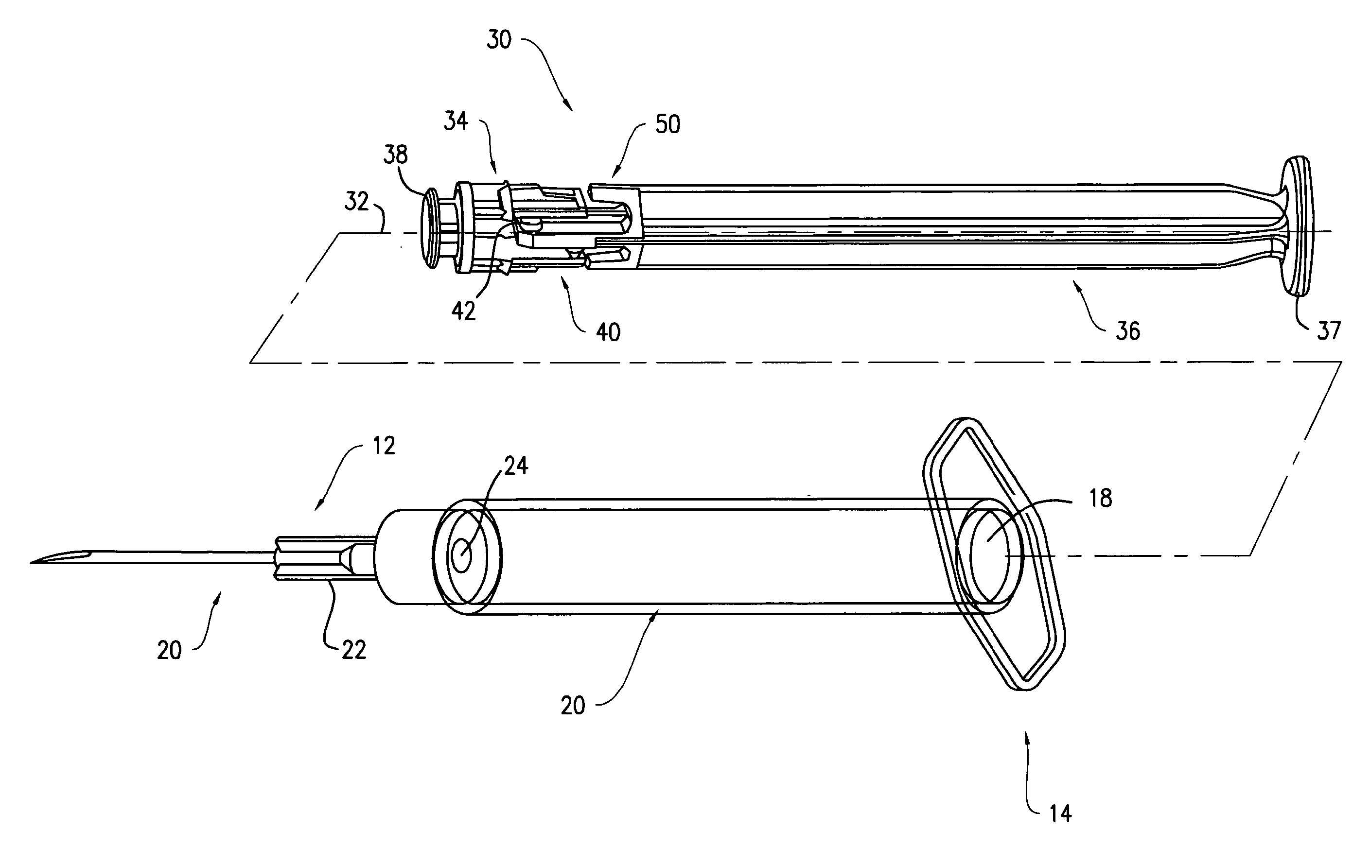
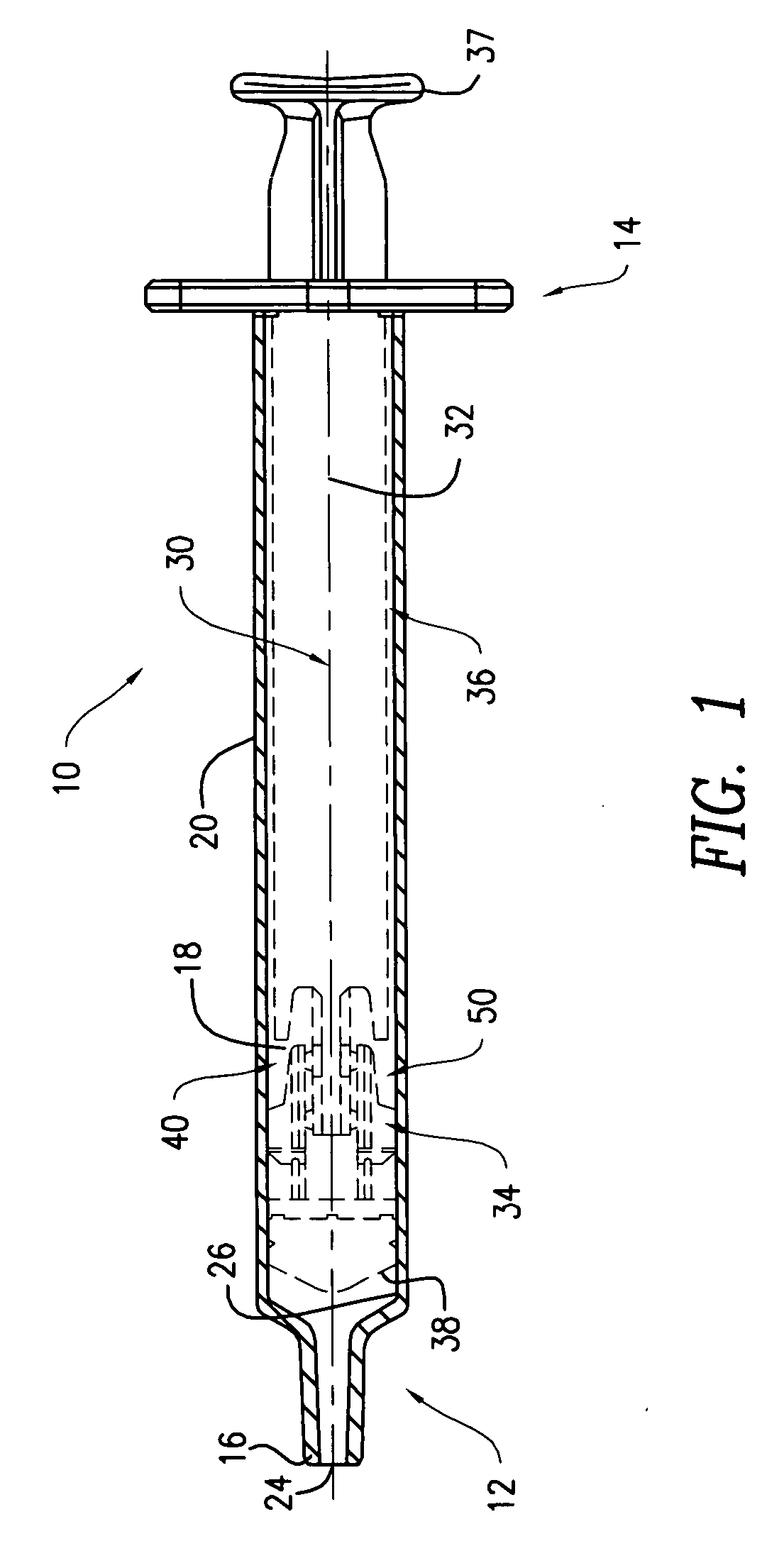
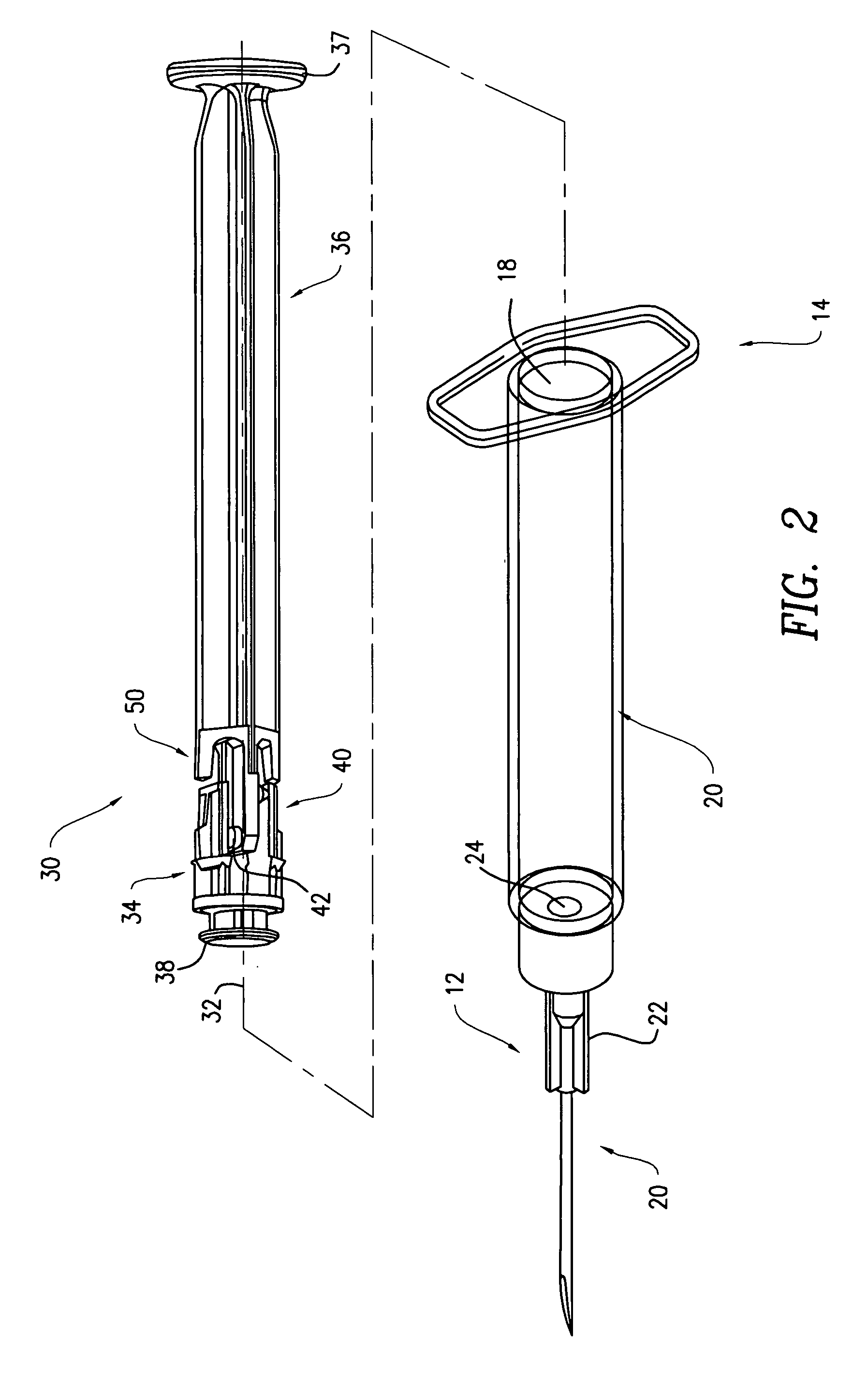
[0023] According to a one embodiment of the invention depicted in FIGS. 1 and 2, a syringe 10 includes a barrel 20 having an internal surface 26 defining a fluid chamber 18, a distal end 12, a proximal end 14, a distal tip 16, and a breakable or collapsible plunger rod 30. The collapsible plunger rod 30 may be slidably disposed within the barrel 20. The plunger rod 30 includes a distal portion 34, a proximal portion 36 and a stopper 38 connected to the distal po...
PUM
Abstract
A syringe including a plunger rod assembly including a proximal portion a distal portion with a stopper for expelling fluids from the syringe and a breakable connection between the proximal portion and the distal portion is disclosed. An impulse reduction system, which may be an elastic element or braking surfaces, reduces the contact impulse imparted by the proximal portion upon the distal portion when the connection between the distal portion and proximal portion breaks is also disclosed.
Description
CROSS-REFERENCE TO RELATED APPLICATIONS [0001] This application is a continuation of U.S. patent application Ser. No. 10 / 835,848 filed Apr. 30, 2004 which is a continuation of U.S. patent application Ser. No. 10 / 256,607 filed Sep. 27, 2002, now abandoned, and a continuation-in-part of U.S. patent application Ser. No. 10 / 706,795 filed Nov. 12, 2003, which is a continuation of U.S. patent application Ser. No. 09 / 941,030 filed Aug. 28, 2001, now abandoned, which is a continuation of U.S. patent application Ser. No. 09 / 274,117 filed May 14, 2001, now U.S. Pat. No. 6,361,525, which is a continuation-in-part of U.S. patent application Ser. No. 09 / 249,431 filed on Feb. 12, 1999, now abandoned, which is a continuation-in-part of U.S. application Ser. No. 09 / 124,447 filed Jul. 28, 1998, now abandoned.BACKGROUND [0002] Embodiments of the invention generally relate to impulse-reduction devices on breakable plunger rod assemblies for medical devices, such as syringes. [0003] The re-use of medic...
Claims
Application Information
Patent Timeline
Application Date:The date an application was filed.
Publication Date:The date a patent or application was officially published.
First Publication Date:The earliest publication date of a patent with the same application number.
Issue Date:Publication date of the patent grant document.
PCT Entry Date:The Entry date of PCT National Phase.
Estimated Expiry Date:The statutory expiry date of a patent right according to the Patent Law, and it is the longest term of protection that the patent right can achieve without the termination of the patent right due to other reasons(Term extension factor has been taken into account ).
Invalid Date:Actual expiry date is based on effective date or publication date of legal transaction data of invalid patent.