Media center

a technology for media centers and cabinets, applied in the field of cabinets for housing and supporting video screens and audiovideo equipment, can solve the problems of difficult repositioning of large units at the desired location, and difficult system changes, etc., and achieve the effect of easy repositioning and easy repositioning

Inactive Publication Date: 2006-08-10
NUCRAFT FURNITURE
View PDF30 Cites 11 Cited by
  • Summary
  • Abstract
  • Description
  • Claims
  • Application Information

AI Technical Summary

Benefits of technology

[0004] The present invention provides a cabinet system or media center that includes a wall portion or panel for supporting or back-dropping a video display and a cabinet or housing portion that houses electronic accessories, such as audio-video equipment and the like. The cabinet may be movably mounted to the display wall portion so that the cabinet may be readily moved away from the display wall portion for accessing wires and cables between the cabinet and the display wall portion, and may be readily moved back to the appropriate location and orientation relative to the display wall portion after the servicing or changeover or adjustment is completed. The movable or adjustable mounting structure or arrangement or element allows the cabinet to be moved from the display wall portion, while the display wall portion stays in the desired position at or near or against the wall of the room, and provides proper indexing or alignment of the cabinet back to the initial position relative to the display wall portion. The media center provides routing of the wires and cables of the electronic accessories or components through the cabinet and display wall portion such that the wires and cables are substantially not viewable to a person at and / or viewing the media center.
[0010] The present invention also provides a media center with one or more channel members and / or one or more display panels and / or columns and / or one or more cabinets or housing portions, in various configurations and combinations, depending on the particular appearance and functionality of the media center. The channel member may be positioned along the floor of the room and along a wall of the room, with the columns and display panels supported on the channel member and thus also supported on the floor, and not supported on or by the wall of the room (but may be attached to the wall to limit or substantially preclude tipping away from the wall, without affecting the scope of the present invention). Installation of the media center is thus enhanced, and the columns and display panels may be arranged and located anywhere along the walls of the room without having to align with studs or the like in the walls, such that the media center of the present invention provides enhanced planning flexibility. The columns, display panels and channel member or members facilitate routing of the wires and cables of the various electronic components throughout the media center while concealing the wires and cables from view. The cabinet or cabinets is / are movably mounted to the channel member and / or to the column / panel so that the cabinet / cabinets may be readily pulled out or moved from the channel member / column / panel and pushed back or moved back into the appropriate or desired location at the channel member / column / panel.

Problems solved by technology

Because the wiring is loosely routed out the back of the cabinet and to the respective components or speakers and / or television, the wiring may become tangled or intertwined, which may make changes to the system very difficult and time consuming.
Such movement of large units is typically very difficult and it may also be difficult to reposition the unit back at the desired location along the wall after the changeover or adjustments are completed.

Method used


Image

  • Media center
  • Media center
  • Media center

Examples


Embodiment Construction

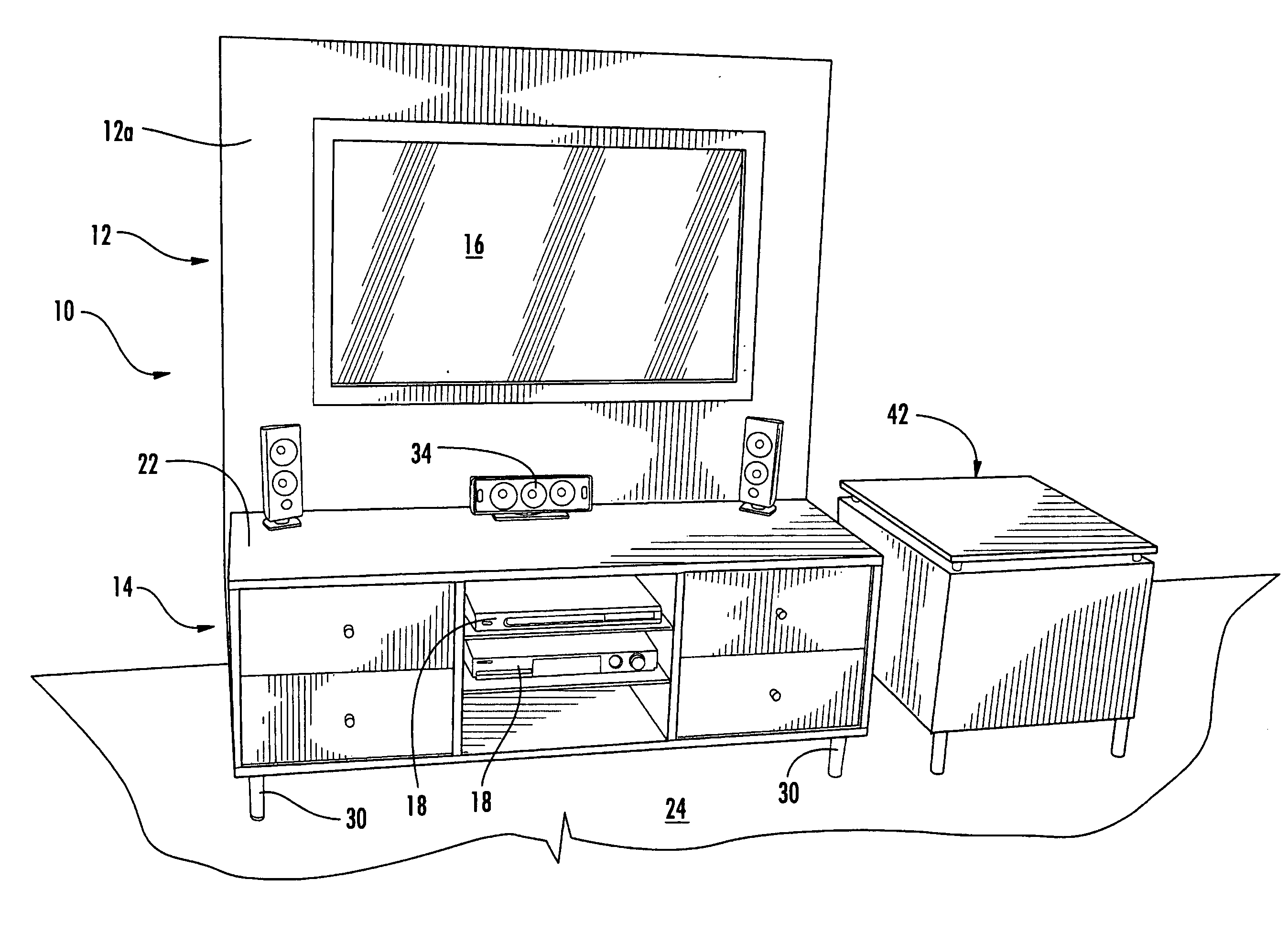
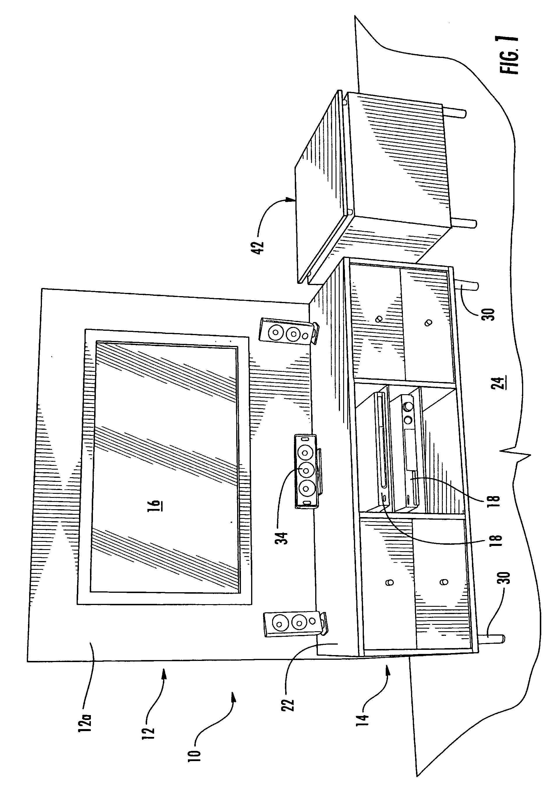
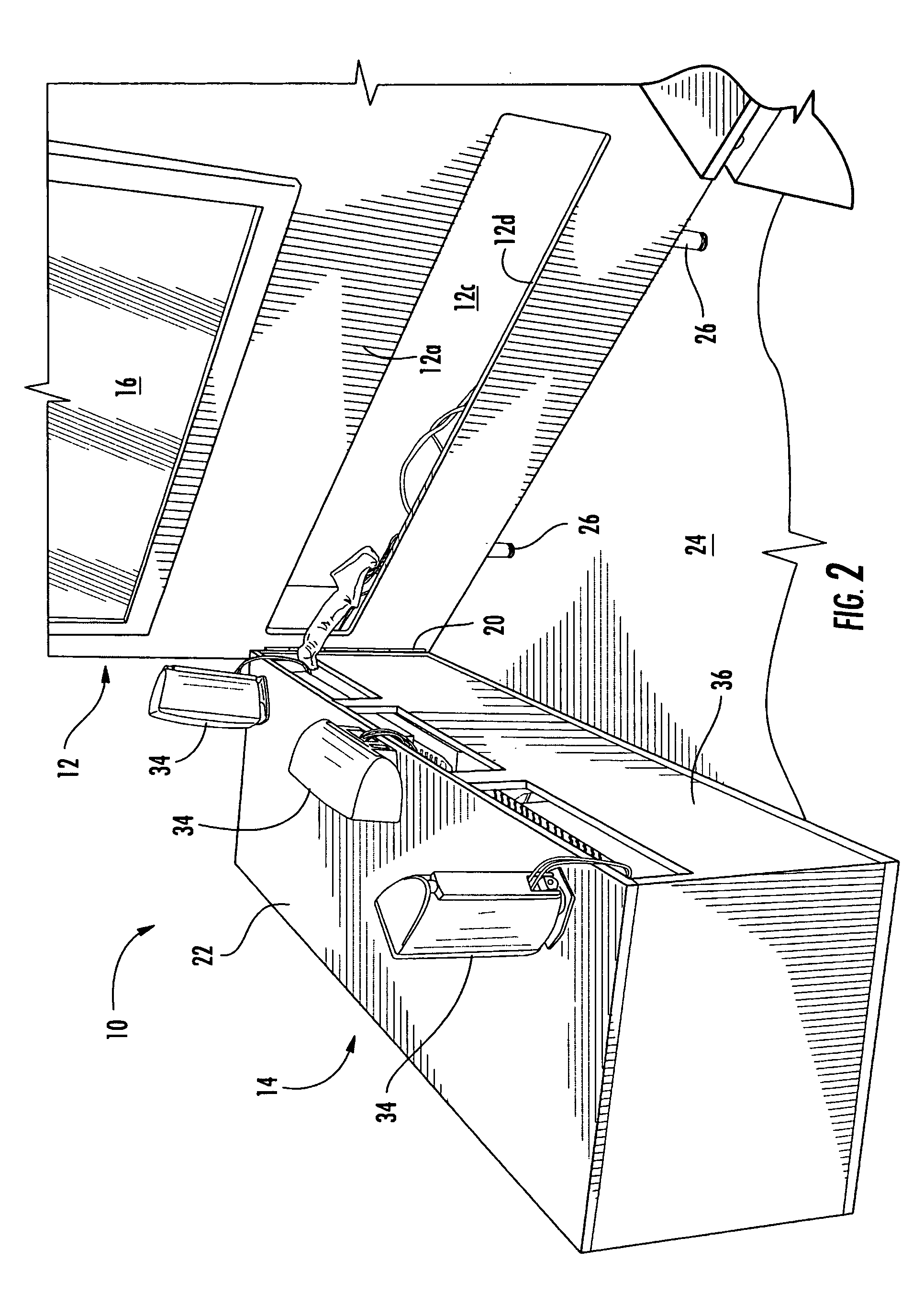
[0027] Referring now to the drawings and the illustrative embodiments depicted therein, a media center 10 (such as an entertainment center for holding audio-video equipment in a residential type application) has a display panel or portion 12 and a cabinet or housing portion 14 movably or adjustably attached to the display panel 12 (FIGS. 1-3). Display panel 12 is configured to support or back-drop a video display 16, such as a plasma screen television or a movie screen for a video projection device or the like. Cabinet 14 is configured to support or house or contain audio-video equipment or components (shown generally at 18 in FIG. 1), such as a DVD player, a receiver, an amplifier, a CD player and / or the like. Cabinet 14 movably attached or mounted to display panel 12 via an adjustment or attachment mechanism or structure 20 (FIGS. 2 and 3), such that the cabinet 14 is movable between a use position (FIG. 1), where the cabinet is substantially abutted against a lower portion of the...


PUM


Abstract

A media center for housing audio-video equipment and displaying a video display includes a cabinet for housing electronic components, a display panel or column, and an adjustable attachment. The display panel defines a cavity for routing wires of the electronic components. The cabinet is movably attached to the display panel via the adjustable attachment, and is movable relative to the display panel between a use position, where the rear portion of the cabinet is substantially abutted against the display panel, and a service position, where the rear portion of the cabinet is at least partially spaced from the display panel for accessing the wires of the electronic components. The display panel may be supported on a channel member that defines a routing cavity therealong for routing wires of the electronic components.

Description

CROSS REFERENCE TO RELATED APPLICATION [0001] The present application claims benefit of U.S. provisional application Ser. No. 60 / 650,846, filed Feb. 8, 2005, which is hereby incorporated herein by reference in its entirety.FIELD OF THE INVENTION [0002] The present invention relates generally to cabinets for audio-video equipment and, more particularly, to cabinets for housing and supporting a video screen and audio-video equipment. Aspects of the present invention are suitable for cabinets for residential applications and for commercial applications, such as in a conference room or the like. BACKGROUND OF THE INVENTION [0003] It is known in the art to provide a cabinet that houses audio-video equipment, such as stereo equipment, DVD players and the like. The cabinet may be positioned at and spaced from a wall of a room, and a television or video screen may be placed on or in the cabinet. The wiring from the components is routed out the rear of the cabinet and between the cabinet and...

Claims


Application Information

Patent Timeline
Patent Type & Authority Applications(United States)
IPC IPC(8): H04N7/18
CPCA47B81/06A47B88/0485A47B88/42
Inventor SCHMIEDER, VALERIE L.BOCKHEIM, ROBERT J.PIKE, CHRISTOPHER A.JONES, PHILLIP A.FEDRIGO, MICHAELSURMAN, ROBERT J.BOCKHEIM, DANIEL J.
Owner NUCRAFT FURNITURE
Why Eureka
Try Eureka