Method and apparatus for combustion of residual carbon in fly ash

a technology of residual carbon and fly ash, which is applied in the field of fly ash processing, can solve the problems of reducing the usefulness of ash as a byproduct, and increasing the processing cost per ton, so as to reduce the levels of residual carbon, reduce the level of carbon remaining in the ash, and ensure the effect of combustion

Inactive Publication Date: 2006-08-17
CONSOL ENG
View PDF70 Cites 53 Cited by
  • Summary
  • Abstract
  • Description
  • Claims
  • Application Information

AI Technical Summary

Benefits of technology

[0009] Briefly described, the present invention comprises a method and system for processing fly ash particles to combust and reduce levels of residual carbon within the fly ash. The system and method of the present invention is designed to expose the fly ash to oxygen and temperature at sufficient levels, and with sufficient residence time, to cause combustion of residual carbon within the ash so as to substantially reduce the levels of carbon remaining in the ash.
[0010] The system generally includes a feed source of fly ash in flow communication with an array of processing units in which the residual carbon in the fly ash is combusted. Generally, the system includes a fly ash feed source in flow communication with a diverter that diverts batches of fly ash to two or more combustion units in which the fly ash is combusted, thereby reducing the carbon content to an appropriate level. After processing, the processed batches of fly ash can be collected from the combustion units in a line or a vessel for further handling.
[0013] As the fly ash within the particulate bed is subjected to entraining forces from the heated airflow, the fly ash particles generally are caused to migrate through the particulate bed. The particulate bed provides a large thermal mass for heat exchange between the fly ash particles and helps promote greater residence time of the fly ash within the reactor chamber to promote ignition and combustion of the residual carbon. The combustion of the carbon of the fly ash is continued as the fly ash particles are passed from the particulate bed and are conveyed through an upper region of the reactor chamber in a dilute suspension or phase, entrained within the heated air flow, and directed toward the outlet of the reactor. While being conveyed in this dilute phase through the upper region of the reactor chamber, the fly ash particles are further exposed to oxygen to enhance the combustion of carbon from the fly ash.

Problems solved by technology

Most fly ash produced by coal combustion, however, generally contains a significant percentage of fine, unburned carbon particles, sometimes called “char”, that reduces the ash's usefulness as a byproduct.
If the carbon levels of the fly ash are too high, the ash cannot be used in many of the aforementioned applications.
The primary problems that have faced most commercial methods in recent years generally have been the operational complexity of such systems and maintenance issues that have increased the processing costs per ton of processed fly ash, in some cases, to a point where it is not economically feasible to use such methods.
At the high temperatures typically required for ash processing, however, such mechanisms often have proved difficult to maintain and operate reliably.
In addition, such mechanisms typically limit the exposure of the carbon particles to free oxygen by constraining or retaining the ash within baskets or on mesh belts such that combustion is occasioned by, in effect, diffusion through the ash, thereby retarding the effective throughput through the system.
These factors generally result in a less effective and costlier process.
These systems have, however, been found to have limited through-put of ash due to effective carbon combustion rates with required carbon particle residence times generally being close to those of other conventional systems.

Method used


Image

  • Method and apparatus for combustion of residual carbon in fly ash
  • Method and apparatus for combustion of residual carbon in fly ash
  • Method and apparatus for combustion of residual carbon in fly ash

Examples


Embodiment Construction

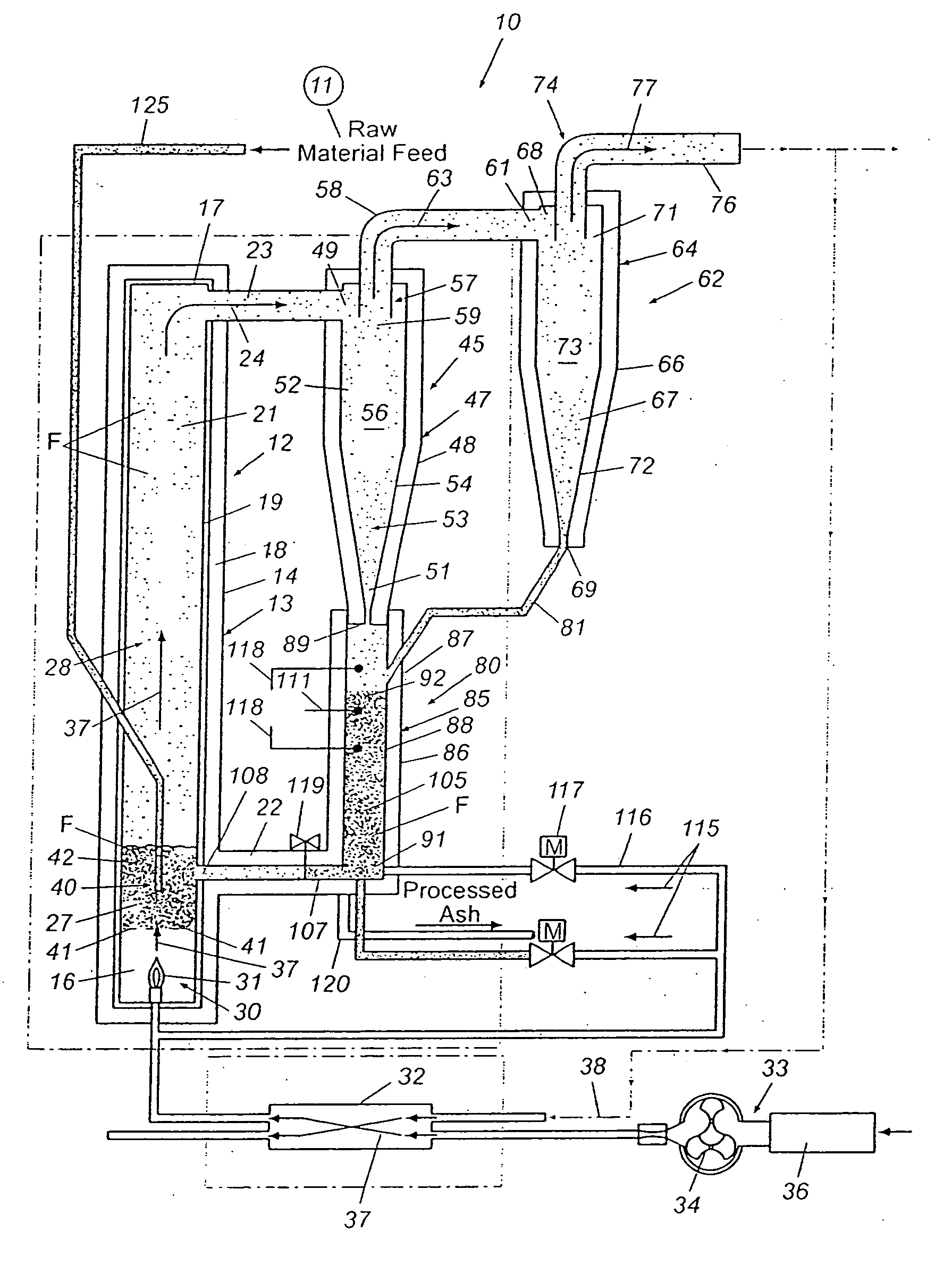
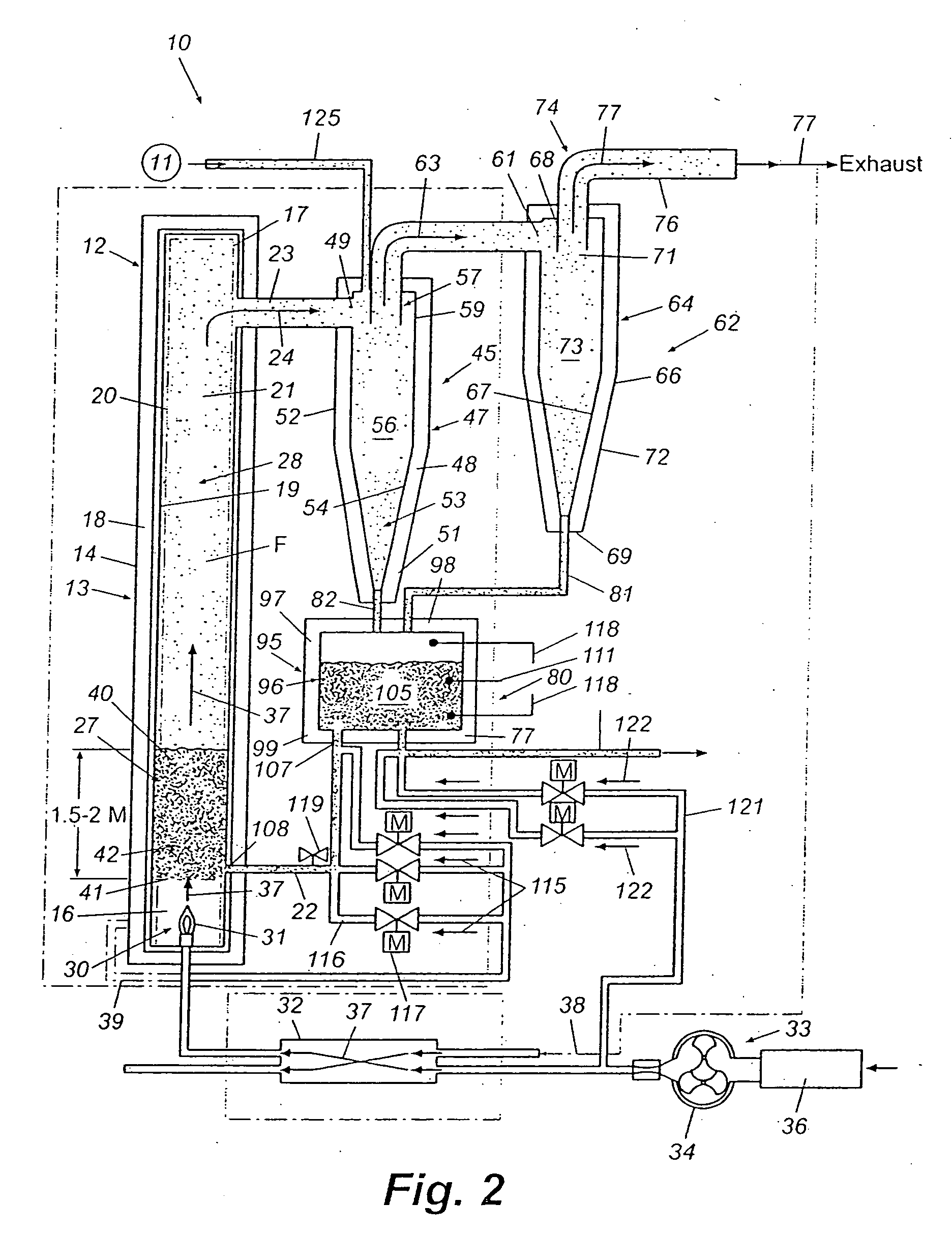
[0022] Referring now in greater detail to the drawings in which like numerals indicate like parts throughout the several views, FIGS. 1-4 illustrate systems in which fly ash can be processed in order to reduce the concentration of residual carbon. As shown in FIG. 4, the present invention encompasses a system 100 including an array of combustion units 110, 111, 112 in which fly ash can be processed, such as by combustion, to reduce the residual carbon of the ash. Although system 100 is shown with three combustors or process units 110, 111 and 112, the array generally can include two or more units, such that greater or lesser numbers of combustors can be used in the system 100 of the present invention. The combustors 110, 111, and 112 of the array generally comprise batch loaded circulating fluid bed combustors (CFBC) that comprise dilute phase ash combustor (DPAC) units, as shown in FIGS. 1-3 and described herein, positioned in spaced series along an ash transport line or path 160 f...


PUM

PropertyMeasurementUnit
temperatureaaaaaaaaaa
temperaturesaaaaaaaaaa
velocitiesaaaaaaaaaa

Abstract

A system for combustion and removal of residual carbon within fly ash particles in which the fly ash particles are fed into an array of process units for combustion. The fly ash particles are subjected to heat and motive air such that as the fly ash particles pass through the particulate bed, they are heated to a sufficient temperature to cause the combustion of the residual carbon within the particles. The fly ash particles thereafter are conveyed in a dilute phase for further combustion through the reactor chamber away from the particulate bed and exhausted to an ash capture. The fly ash is then separated from the exhaust air that conveys the ash in its dilute phase with the air being further exhausted and the captured fly ash particles being fed to a feed accumulator for re-injection to the reactor chamber or discharge for further processing.

Description

CROSS-REFERENCE TO RELATED APPLICATIONS [0001] This application is a continuation of co-pending U.S. patent application Ser. No. 10 / 686,149, filed Oct. 15, 2003, incorporated by reference herein in its entirety, which is a continuation-in-part of U.S. patent application Ser. No. 10 / 254,747, filed Sep. 25, 2002, which is a continuation of U.S. patent application Ser. No. 09 / 705,019, filed Nov. 2, 2000 (now U.S. Pat. No. 6,457,425), which claimed the benefit of U.S. Provisional Application No. 60 / 162,938, filed Nov. 2, 1999. [0002] This application also claims the benefit of U.S. Provisional Application No. 60 / 418,659, filed Oct. 15, 2002.FIELD OF THE INVENTION [0003] The present invention generally relates to the processing of fly ash. In particular, the present invention relates to methods and systems for reducing residual carbon in fly ash. BACKGROUND [0004] Coal is still today one of the most widely used fuels for the generation of electricity with several hundred power plants in ...

Claims


Application Information

Patent Timeline
Patent Type & Authority Applications(United States)
IPC IPC(8): F23J1/00F23B90/00F23G5/30F23J15/02
CPCF23G5/30F23G2203/501F23G2203/503F23G2209/30F23J1/00F23J15/02F23J2217/40F23J2900/01007F23J3/00F23B7/00
Inventor CRAFTON, PAUL M.LEWIS, JAMES L. JR.THOME, WILLIAM
Owner CONSOL ENG
Why Eureka
Try Eureka