Braking assembly for a roller skate

Inactive Publication Date: 2006-08-17
TREMBLAY NORMAND
View PDF26 Cites 8 Cited by
  • Summary
  • Abstract
  • Description
  • Claims
  • Application Information

AI Technical Summary

Benefits of technology

[0016] Advantageously, the braking assembly is ergonomic and provides a relatively efficient and a relatively easy manner way of braking, either to completely stop the intended user or to modulate his speed.
[0017] In addition, the braking assembly is relatively easily integrated into currently existing roller skates and is relatively inexpensive to manufacture. Furthermore, the braking assembly is relatively robust, relatively light, requires a

Problems solved by technology

However, currently existing brakes of this type only provide for a relatively slow decrease in speed.
Since in recent years skates have improved greatly and are not solely used by children but also by well-trained adults, this type of braking technique is relatively inefficient in view of the speeds attained using these roller skates.
In addition, using this type of brake requires some skill by the user and may create some difficulty for the user to remain in balance.
However, it is mainly beginner skaters that are most likely to need braking in case of emergency, as they are relatively inexperienced with the skate.
Having to learn the skill for braking in this beginning phase is therefore a disadvantage of currently existing braking assemblies.
However, it requires a relatively hard to acquire skill.
Also, this technique causes a relatively large amount of wear of the wheels, which are not typically designed to withstand forces produced by this braking technique.
However, such cable-actuated braking assemblies have been relatively u

Method used


Image

  • Braking assembly for a roller skate
  • Braking assembly for a roller skate
  • Braking assembly for a roller skate

Examples


Embodiment Construction

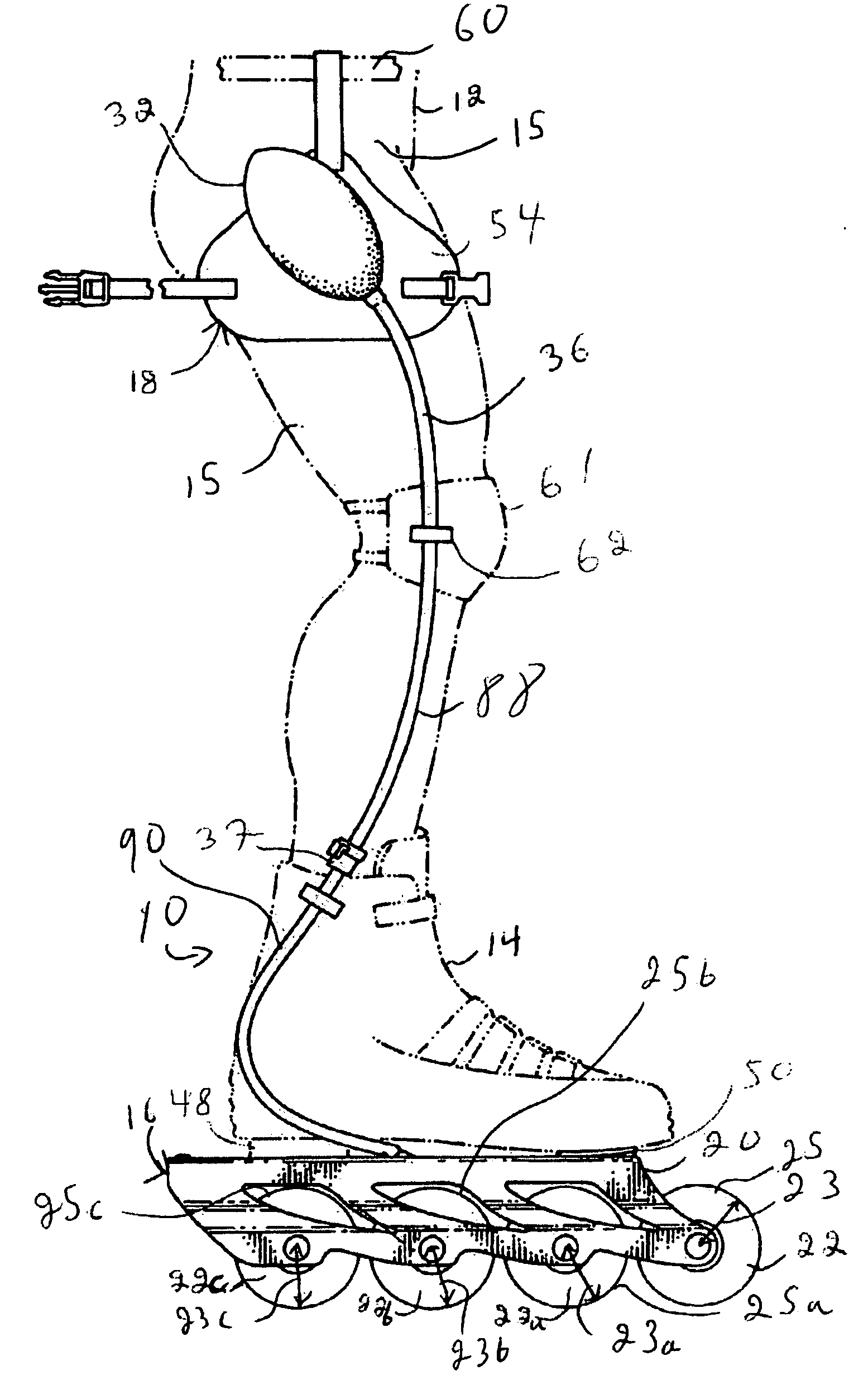
[0034]FIG. 1 illustrates a roller skate 10 for use by an intended user 12, only the leg 13 and waist 15 thereof being shown in the drawings. The intended user 12 has a foot (not shown in the drawings) and uses the roller skate 10 onto a surface (both not shown in the drawings).

[0035] The roller skate 10 includes a foot receiving portion in the form of a skate boot 14 for receiving the foot of the user 12. The roller skate 10 further includes a roller assembly 16 coupled to the skate boot 14. Furthermore, the skate 10 includes a braking assembly 18 operatively coupled to the roller assembly 16 so as to be able to modulate the speed of the intended user 12 when he uses the roller skate 10.

[0036] The skate boot 14 is any suitable skate boot. Such skate boots are well known in the art and the skate boot 14 will therefore not be described in further details. Also, in alternative embodiments of the invention, the skate 10 includes any other suitable foot receiving portion.
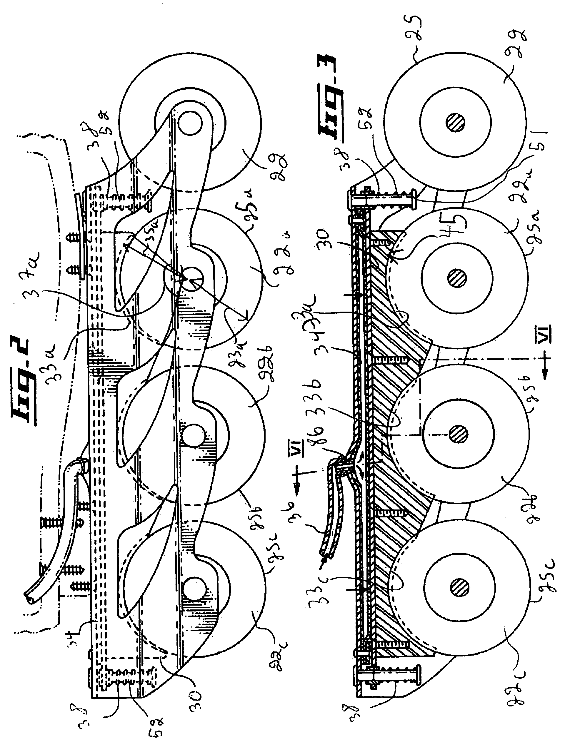
[0037] The ro...


PUM


Abstract

A braking assembly for use with a roller skate, the roller skate being wearable by an intended user having a leg, a foot extending from the leg and a hand. The roller skate has a frame, a foot receiving portion coupled to the frame for receiving the foot of the user and first and second wheels rotatably mounted to the frame, the first and second wheels defining respectively a first wheel radius and a second wheel radius. The first and second wheels further define respectively a first wheel circumferential surface and a second wheel circumferential surface. The braking assembly includes a brake shoe defining a wheel contacting surface, the wheel contacting surface including a first arc segment and a second arc segment for respectively abutting against a portion of the first and second wheel circumferential surfaces, the brake shoe being mountable to the roller skate such as to be movable between a released position and an engaged position, wherein in the released position, the brake shoe is substantially spaced apart from the first and second wheel circumferential surfaces and in the engaged position, the first arc segment frictionally abuts against a portion of the first wheel circumferential surface and the second arc segment frictionally abuts against a portion of the second wheel circumferential surface; and an actuator operatively coupled to the brake shoe for selectively moving the brake shoe between the released and engaged positions.

Description

[0001] This application claims priority from U.S. Provisional Patent Application Ser. No. 60 / 651,972 filed Feb. 14, 2005.FIELD OF THE INVENTION [0002] The present invention relates to roller skates. More specifically, the present invention is concerned with a braking assembly for a roller skate. BACKGROUND OF THE INVENTION [0003] There are many techniques and devices usable to slow down or stop while roller-skating. For example, in some roller skates, a brake in the form of a pad of material is provided at one or both extremities of the skate. Then, to brake, the skate user simply tilts his skates so that the block abuts against the surface onto which he is skating. By exerting a suitable pressure with his leg onto the brake pad, the user can control his speed. [0004] However, currently existing brakes of this type only provide for a relatively slow decrease in speed. Since in recent years skates have improved greatly and are not solely used by children but also by well-trained adul...

Claims


Application Information

Patent Timeline
IPC IPC(8): A63C17/14
CPCA63C17/06A63C17/1409A63C2017/1472
Inventor TREMBLAY, NORMAND
Owner TREMBLAY NORMAND
Why Eureka
Try Eureka