
UWB antenna with unidirectional radiation pattern

a technology of unidirectional radiation and antenna, which is applied in the direction of antennas, antenna feed intermediates, electrical devices, etc., can solve the problem of not being able to obtain a directional radiation pattern

Active Publication Date: 2006-08-17
SAMSUNG ELECTRONICS CO LTD
View PDF7 Cites 27 Cited by
  • Summary
  • Abstract
  • Description
  • Claims
  • Application Information

AI Technical Summary

Problems solved by technology

However, a directional radiation pattern can not be obtained due to having a small-sized antenna.

Method used


Image

  • UWB antenna with unidirectional radiation pattern
  • UWB antenna with unidirectional radiation pattern
  • UWB antenna with unidirectional radiation pattern

Examples


Embodiment Construction

[0053] Hereinafter, exemplary embodiments of the present invention will be described in detail with reference to the accompanying drawing figures.

[0054] In the following description, same drawing reference numerals are used for the same elements even in different drawings. The matters defined in the description such as a detailed construction and elements are provided to assist in a comprehensive understanding of the invention. Thus, it is apparent that the present invention can be carried out without those defined matters. Also, well-known functions or constructions are not described in detail since they would obscure the invention in unnecessary detail.

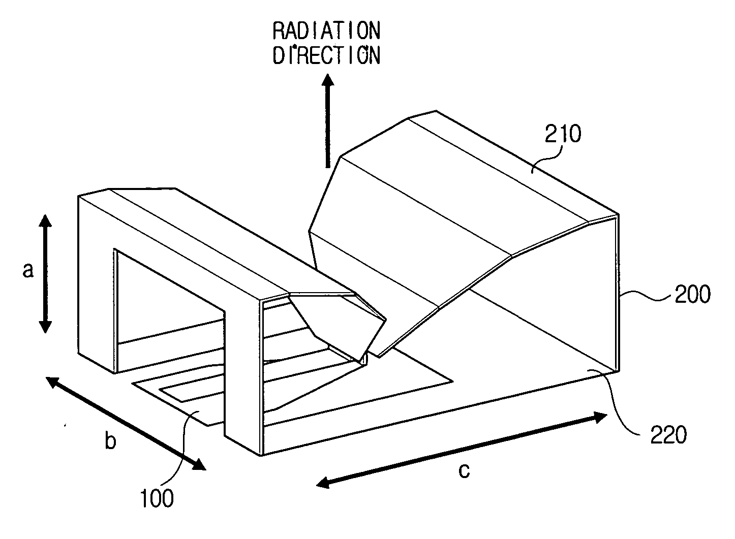
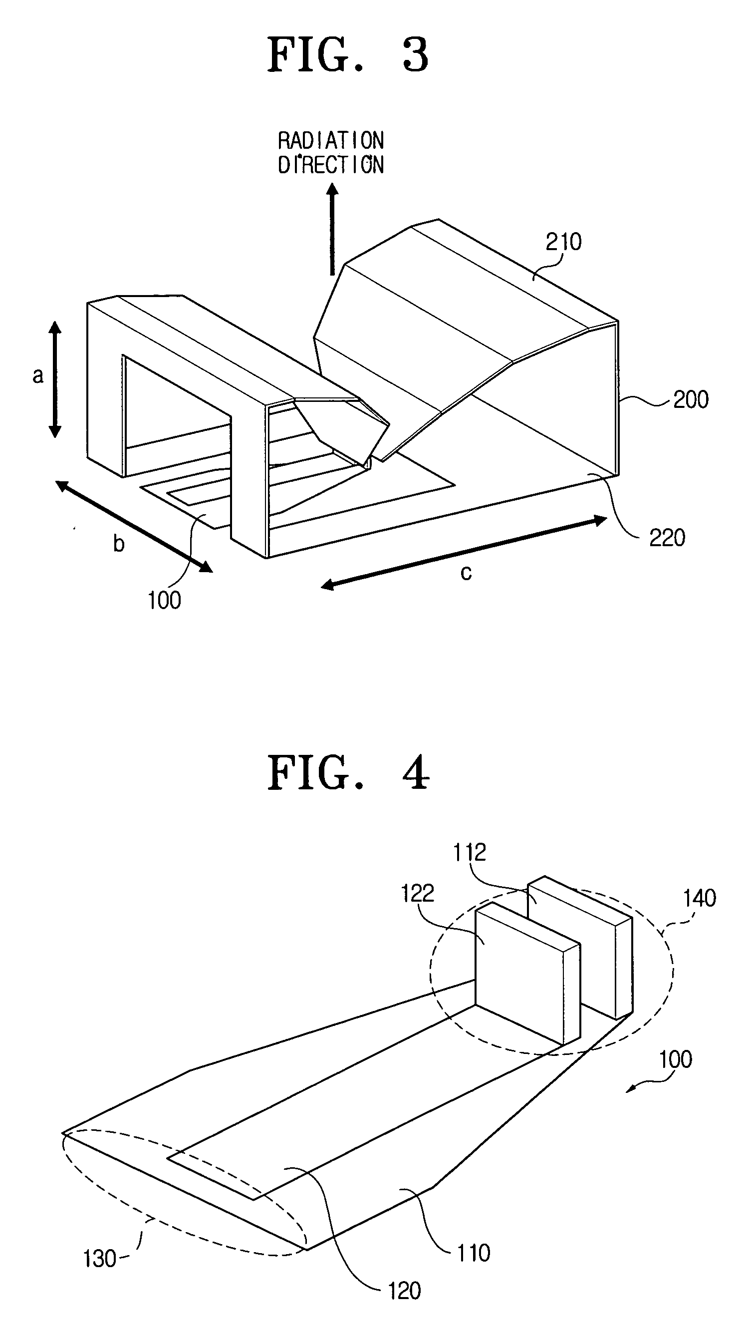
[0055]FIG. 3 is a perspective view of a UWB antenna according to a first exemplary embodiment of the present invention, and FIG. 4 is a perspective view of the power feeder applied to the UWB antenna of FIG. 3.

[0056] Referring to FIG. 3, a UWB antenna according to the first exemplary embodiment of the present invention includes a...


PUM


Abstract

An ultra wide band (UWB) antenna with a unidirectional radiation pattern, including: a power feeder including a connecting point at one end and a feeding point at the other end; and a radiator including a dipole part, connected with the feeding point on the basis of the feeding point, and a loop part, whose both ends are connected with both ends of the dipole part respectively to be closed-loop-shaped. Accordingly, a UWB antenna with a unidirectional radiation pattern which mainly performs radiation perpendicular to an antenna plane can be provided.

Description

CROSS-REFERENCE TO RELATED APPLICATIONS [0001] This application claims priority from Korean Patent Application No. 10-2005-0012751 Feb. 16, 2005 and 10-2006-0000149 filed Jan. 2, 2006 in the Korean Intellectual Property Office, the entire contents of which are incorporated herein by reference. BACKGROUND OF THE INVENTION [0002] 1. Field of the Invention [0003] Apparatuses consistent with the present invention relate to an ultra wide band (UWB) antenna with a unidirectional radiation pattern, and particularly, to a UWB antenna with a unidirectional radiation pattern which mainly performs radiation perpendicular to an antenna plane. [0004] 2. Description of the Related Art [0005] In general, a communications system uses a frequency of a particular band to transmit data. Circuit data and packet data are data used in a communications system. [0006] Circuit data are data such as a voice signal for real-time transmission / reception. Packet data are more than a certain size and does not nec...

Claims


Application Information

Patent Timeline
IPC IPC(8): H01Q9/16
CPCH01Q7/00H01Q5/50H01Q5/364H01Q9/26
Inventor KWON, DO-HOONKIM, YONG-JINLEE, SEONG-SOO
Owner SAMSUNG ELECTRONICS CO LTD
Learn More