Compact ultra-wide bandwidth antenna with polarization diversity

a polarization diversity, ultra-wide bandwidth technology, applied in the direction of antennas, elongated active element feeds, antenna feed intermediates, etc., can solve the problems of limited bandwidth, large, complex multiple bean antennas, and inability to exploit spatial diversity, and achieve low mutual coupling

Active Publication Date: 2011-12-08
MITRE SPORTS INT LTD
View PDF3 Cites 11 Cited by
  • Summary
  • Abstract
  • Description
  • Claims
  • Application Information

AI Technical Summary

Benefits of technology

[0023]The systems and methods of the present invention provide a number of advantages. One advantage of the present invention is that it provides a compact antenna suitable for MIMO polarization diversity, for use as a CRPA antenna, and / or for navigation, communication, radar and other wideband systems. The antenna of the present invention can exhibit a 2:1 frequency bandwidth, overall size less than ¼ wavelength diameter, and a height at the lowest frequency of operation.
[0024]Although the present invention is compact, it provides a wide bandwidth, right-hand circular polarization, left-hand circular polarization, and tri-axial orthogonal linear polarizations. Another advantage of the present invention is that it can produce wideband sector nulls in desired directions.
[0025]Another advantage of the present invention is that the impedance, gain and radiation patterns do not substantially change with frequency. In turn, phase and amplitude weights used for nulling do not have to be adjusted for a different frequency. Another advantage of the present invention is that there is low mutual coupling between the monocone monopole antenna and the two biconical dipole antennas.

Problems solved by technology

Thus, spatial diversity can only be exploited when sufficient real estate is available.
Multiple bean antennas are typically complex, large, expensive, often have a limited bandwidth and typically have side lobes that can reduce their effectiveness.
Although polarization diversity can immunize a system from polarization mismatches that would otherwise cause signal fade, current polarization diversity antennas are not compact and do not have a wide frequency bandwidth.
GPS and GNSS systems are susceptible to intentional and unintentional interference (e.g., jamming, a technique used by adversaries to distort signals).
Existing CRPAs have limited bandwidth, rendering them unsuitable for use over numerous frequencies or over wide bandwidths (e.g., GNSS or GPS).
CRPAs can also form very narrow nulls and are limited in the number of interfering sources that can be nulled.
In addition, CRPAs are usually large (e.g., 35 centimeters in diameter) making them unusable on equipment that lacks sufficient mounting space (e.g., small missiles).

Method used


Image

  • Compact ultra-wide bandwidth antenna with polarization diversity
  • Compact ultra-wide bandwidth antenna with polarization diversity
  • Compact ultra-wide bandwidth antenna with polarization diversity

Examples


Embodiment Construction

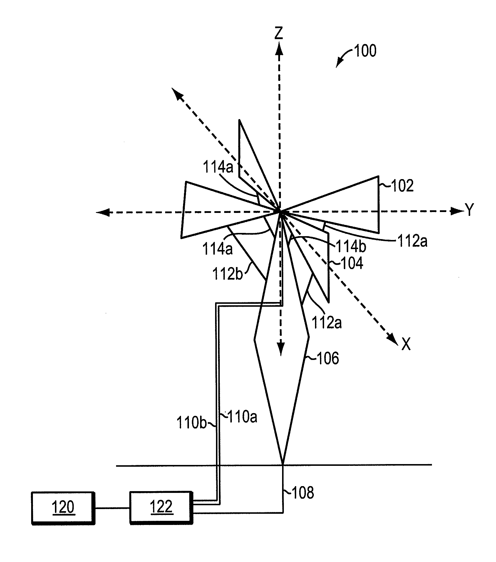
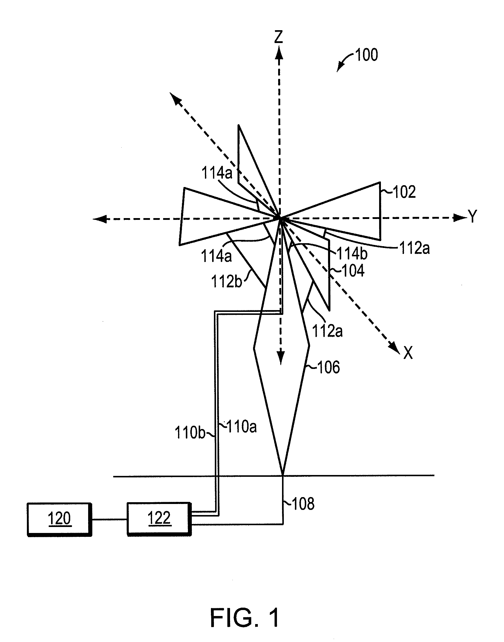
[0033]FIG. 1 is diagram 100 showing an exemplary antenna system, according to an embodiment of the present invention. The antenna system includes a first biconical dipole antenna 102, a second biconical dipole antenna 104, a monocone monopole antenna 106, a first feed line 108 to the monocone monopole antenna 106, a second feed line 110a to the first biconical dipole antenna 102, a third feed line 110b to the second biconical dipole antenna 104, and a first biconical dipole antenna shunt 112a, a second biconical dipole antenna shunt 112b, a third biconical dipole antenna shunt 114a, and a fourth biconical dipole antenna shunt 114b, an antenna feed system 122, and a transmitter / receiver 120.

[0034]The first biconical dipole antenna 102 disposed substantially orthogonal to the second biconical dipole antenna 104. The monocone monopole antenna 106 is disposed substantially perpendicular to a ground plane 116 and between the two biconical dipole antennas 102 and 104. The spatial relation...


PUM

PropertyMeasurementUnit
impedanceaaaaaaaaaa
diameteraaaaaaaaaa
frequencyaaaaaaaaaa

Abstract

Described are methods and apparatus, including a method of manufacture, for a compact antenna. Two biconical dipole antennas and a monocone monopole antenna are displaced in an adjacent and orthogonal configuration. The two biconical dipole antennas are each shunted to the monocone monopole antenna.

Description

GOVERNMENT RIGHTS[0001]The technology described herein was developed with funding provided by the USAF GPS Wing organization, contract number: FA8721-10-C-0001. The government may have rights in the technology.FIELD OF THE INVENTION[0002]The invention relates generally to antennas for receiving and transmitting electromagnetic waves, including methods of manufacturing a compact antenna, and methods for increasing impedance bandwidth in a compact antenna.BACKGROUND[0003]As demand for mobile phone, mobile email, internet access, multimedia services, military communications and other broadband applications increases, the need for high data-rate and high capacity wireless systems increases. However, radio spectrum availability remains substantially constant. Therefore, it is desirable to increase spectral efficiency (more bits per second per hertz of bandwidth) and link capacity without the use of additional bandwidth.[0004]Multiple-input multiple-output (MIMO) wireless technology emplo...

Claims


Application Information

Patent Timeline
Patent Type & Authority Applications(United States)
IPC IPC(8): H01Q21/30H01P11/00
CPCH01Q9/28Y10T29/49016H01Q21/30H01Q9/40
Inventor ELLIOT, PAUL G.ROSARIO, EDDIE N.DAVIS, ROBERT J.
Owner MITRE SPORTS INT LTD
Why Eureka
Try Eureka